My Experience in Programming an INT-422 remote ©MJH 2022-2023;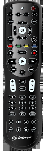
(Content modified: January, 2023)
(File modified: November 18, 2024 3:04 pm)
This site works better with Javascript enabled.
Michael J. Hannah, Los Ranchos, NM.
My Experience in
Programming an INT-422-4 Remote
• Two options for programming commands
Manually Programing Built-in Device Commands
• Finding the right Device Setup codes:
• INT-422-4 Remote and Buttons
• Electronic Device Setup Codes, My Device Codes
• Manually Overriding the Action of a Button
• Manually Key Move a Function
• Manual Key Moves and Macros Details
• Hierarchy of Button Overrides
• INT-422 Non-Standard Hierarchy
• LG TV “Long Press” Functions
• AN-MR19BA Magic remote: Buttons
• AKB75095315 Standard remote: Code table
• Built-in Channel Master DVR+ Device Setup
• RRC9002-0102E remote: Code Table
• Built-in ZVOX Soundbar Device Setup
• Built-in Panasonic DVD/VCR Device Setup
• EUR7659T80 remote: Code Table
• INT-422-4 Combined Built-in Commands
Programming Device Commands with RM software and JP1 hardware
• Connecting the INT-422-4 Remote to the Computer
• First encounter with the RM Programs
.rmir, .rdf, .map, .jpg, .rmdu
• Defining the new INT-422-4 Remote for RM
Generic Names and List
• OEM supplied remote’s view in RMIR
General tab, Devices tab, Raw tab
• After Built-in Device Setup view in RMIR
• INT-422-4 Remote’s Buttons in RMDU
• First RMDU Remote Buttons View
• Normal RM Assignment of a Function to a Button
• Electronic Hardware Device Upgrade Files (.rmdu)
Aspect Ratio Macro, Caption Macro,
Aspect Ratio Macro, Caption Macro,
• My Files
• JP1 Hardware and RM Software Programming
These days nearly all electronic devices come with remotes which are used to control them. Some remotes use InfraRed (IR) signals to communicate with the device, some communicate using an RF signal on some Radio Frequency band. An OEM remote is designed to send an appropriate signal or set of signals to that OEM’s given electronic device when a given button is pressed. That signal will then cause that electronic device to perform the desired function(s). [Remote devices have buttons (often also called keys), electronic devices perform functions triggered by a button press.] All too often the electronic device becomes unusable if its OEM remote become inoperable (no matter how many new batteries you put in it). Now what?
We have had the Dish/PAL DVR+ (Digital Video Recorder) from Channel Master, model CM-7500XRC, since the beginning of 2014. For any problems with it I have always turned to posts by many expert users of this recorder on the “Channel Master DVR+ Owners Thread” within the on-line “Audio/Video Systems” Forum https://www.avsforum.com/threads/channel-master-dvr-owners-thread.1481183/. Over time Channel Master included two different models of remotes with this device which most users have named based on their shape and size. Our very early device, originally bought from Dish Network, came with what is known as the “thin” remote, but later versions had what is known as the “peanut” remote. Both these remotes communicate with the DVR+ using an InfraRed beam (IR). After multiple problems, especially with its coin-sized batteries, our thin remote completely stopped working in early May 2022. (I guess eight years is not bad, but we use this device every day so this was very traumatic.)
Channel Master has long since ceased offering this DVR+ model or its thin (or the later peanut) remote as a product, and now only has a new “simple” remote with extremely reduced controls. So I reconciled myself to purchasing a “universal” remote as a replacement to continue to be able to use the DVR+.
Many “universal” IR replacement remotes have a “learning” mode, where one can teach that remote the IR signals each button should send to execute the appropriate function for a specific electronic device. However, all such “learning” requires having an operational existing remote from which to learn these IR signals to send to the DVR+. (Catch 22: you often only need a replacement when the existing remote is no longer operational!) After much searching among the posts on the DVR+ forum thread it became clear there was one currently marketed device which stood out that I considered a truly viable and nearly complete replacement. The “Inteset 4-in-1 Universal Backlit IR Learning Remote” https://www.amazon.com/gp/product/B00M4I1BAY (generally known as the INT-422 remote) is advertised as able to control up to four devices via IR.
An INT-422 could “learn” from a functioning DVR+ remote if one had one. But absent a working DVR+ remote or the availability to purchase one, an INT-422 has two options to make this “universal” remote send signals “as if” it were a DVR+ remote:
• program a built-in Device Setup code into the remote provided by a universal remote’s manufacturer (e.g. Inteset) to cause the remote to emulate (most of) the signals to control this electronic device, or
• program using JP1 hardware and RM software to construct and upload a set of commands to this universal remote which would emulate any and all signals one chose to define to control one or more specific electronic devices such as the DVR+.
The “good” news is that this Inteset product has both capabilities, and is designed to be able to control up to four electronic devices from this one remote. Inteset does publish their built-in Device Setup codes to cause one of this device’s four sets of device controls to emulate the thin DVR+ remote. (It also provides codes for all my other basic electronic devices). While that “sounds” useful, the bad news is that Inteset provides no detailed documentation about any of their built-in device codes, such as what function each button will now cause that programmed electronic device to perform. One can generally “guess” which buttons now will operate the obvious device functions, but with no reliability for guessing any other more obscure functions. And posts on the Internet indicate their DVR+ built-in device code emulates “nearly” all its controls, but not all. For me a lack of documentation and “nearly” all functions was not good enough, expecially since the one function reported to not be provided was that invoked by the DVR+ “Back” key which we use a lot. To be fair one “can” add that and most any other missing controls manually with Keypad Commands. But since I intend this device to control all my devices, I decided I might as well take the time to learn how to completely program the remote with commands for any device.
The even better news is that these Inteset remotes are made by UEI (Universal Electronics Inc., the largest maker of remotes) and also have a set of “JP1” hardware pins on its back. They allow a hardware interface cable to be attached to directly connect the remote to a PC. With this JP1 hardware plus the custom RM software one can upload and assign an IR code for any electronic device function to any button. Not only does that ensure one could assign “all” functions, but one will explicitly know which button one has assigned which function for every device the remote will control.
An essential aid in this second method is the on-line JP1 Remotes Forum http://www.hifi-remote.com/forums/index.php where a relatively small group of talented and dedicated hackers maintain an open source set of Java programs (RemoteMaster for IR) which run on various PC operating systems. These programs provide a graphical interface to facilitate constructing a set of commands which can then be uploaded and assigned to the buttons of a UEI remote via the JP1 interface cable. Not only do the members of the group maintain the programs, they have developed a repository of files which contain sets of commands to implement the specific codes to cause all the functions of a wide variety of devices (e.g. the DVR+) which can be read into these JP1 programs and then uploaded onto a remote. The ability to use this software to upload commands via a remote’s JP1 hardware pins allows such UEI remotes to be programmed to invoke the functions of nearly any device which is controlled by IR.
The two options to program commands on an INT-422-4
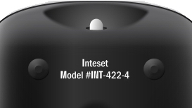 When I bought two of these UEI remotes they came as the latest version 4, thus specifically known as “Model #INT-422-4” as shown at the left on the back of the remote.
Obviously the simplest and easiest option is to manually invoke a built-in Device Setup code for a specific electronic device, such as the DVR+. That will activate this UEI INT-422-4 with built-in commands which invoke that device’s functions by assigning them to appropriate buttons on the remote. The immediately following section describes how this was first done on one of the two remotes (mainly because I immediately needed a working remote for the DVR+). But I also realized (with the absence of any detailed documentation from Inteset about their built-in Device Setup codes) I had to experiment to understand what functions were provided for each electronic device, and on which buttons. One could just augment or overwrite some built-in commands without need of special hardware or software by manually using individual Keypad Commands, but I had “grander” plans.
Later I used JP1 hardware and RM software on the second remote to see how much more I could do with that total programming control. (Although I had hoped they would do so, these special software programs and the cable hardware were unable to extract more details about the above built-in Setup Codes for documentation and comparison.) How I used this hardware and software to program commands into these INT-422-4 remotes for my electronic devices is described in the separate section below. In mist cases this form of programming the remote will eliminate the need for manually programming override codes into the remote.
Manually Programming
Built-in Device commands
on a INT-422-4 remote
Finding the right Device Setup code
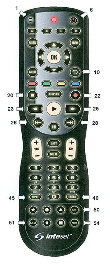
The Inteset model #INT-422-4 is designed to be able to control up to four different electronic devices. Thus the remote requires knowing what is the appropriate complete IR signal to be sent which will be recognized by a specific electronic device to produce a specific function when a given button is pressed on this remote. The following image and table identifies the INT-422-4 remote’s buttons by the names and the button numbers used in its included INT-422-4 User’s Guide. [Remote devices have buttons (often also called keys), electronic devices perform functions based on button presses.]
[For some of the audio/visual HTML icons used in the tables within these notes, see https://en.wikipedia.org/wiki/Media_control_symbols or https://unicode.org/emoji/charts/emoji-list.html#av-symbol. For a complete set of available Unicode 14.0 Character Code charts see https://www.unicode.org/charts/
Note that whether a Unicode symbol will be displayed and what that symbol will look like can greatly depend upon what font is being used by your browser. For this reason this web page links to specific fonts stored on my domain to ensure they do display and most look like the symbols printed on the remotes discussed. For information about what fonts I choose to use and the display of symbols in those fonts see my web page of their Unicode Character Variations.]
Solely for my purposes of distinguishing between them, within these notes I “try” to refer to keys on an electronic device’s OEM remote which is being emulated (or as an entry in an internal key table within the remote) as opposed to physical buttons on the universal INT-422-4 remote doing the emulating. I find these separate terms help me when making comparison descriptions between the OEM and universal remotes (as well as between physical buttons and internal memory key entries) by making the text more readable.
Like most universal remotes the INT-422-4 comes with many preprogrammed built-in tables of IR signals to control a variety of electronic devices. Each table can assign to each button the functions appropriate for that electronic device. Each table is identified and accessed within the remote, and activated on the remote, by a Device Setup code. Inteset provides a lookup web page of all the Device Setup codes built in to their model #INT-422-4 on their company website: https://universalremotes.net/inteset-universal-remote-control-device-code-lookup.html. All INT-422 models use five digit setup codes, where the first digit of these five digit codes generally identifies the type of device. The Inteset INT422-3 Technical Document only mentions the first four (0=Cable, 1=TV, 2=Video, 3=Audio) but most documentation for remotes describe six leading digits for these codes: 0=Cable/SAT/VCR, 1=TV/Combo, 2=Video/VCR/DVD, 3=Audio/DVD/Blu-Ray, 4=CD, 5=Cable/SAT/IPTV/DTA/Other.
It is useful to realize that the last four digits of a Device Setup code have no special meaning and are simply defined by the remote’s manufacturer (not the electronic device’s manufacturer) to provide unique access to their constructed Device Setup tables of device function codes. Thus a Device Setup code number for the DVR+ table of functions on an Inteset remote could be a completely different number for some other remote. Further as is mentioned below, when creating your own file with its table of functions for an electronic device you are free to identify it by any setup code number that you like, in the range 0000 through 2047. But if you use a number that is already defined in this remote's built-in code library, you will override that number, which means you will no longer be able to use that built-in code to access that built-in table of functions, but you won't get an error message or any other notification.
In addition to my main interest due to the dead DVR+ remote I have three other devices I also thought I would to control with this one remote. The following Device Setup codes to access a built-in table of functions for each of these devices were found listed on the Inteset web page mentioned above, with the code that worked for me in bold:
To activate a given built-in Device Setup code’s table of device functions the following steps are required:
[Be sure to have the device (e.g. the DVR+) turned on while trying to assign its code.]
• Press the Device Mode button on the remote you wish to program (e.g.: B).
• Press and hold the SET button until the red LED blinks twice, then release.
• Enter the first five-digit Device Setup code for the device (e.g. 04465) found on the Inteset web page. The LED blinks once as each digit is entered. If the code is one of the remote’s valid internal tables, the LED will blink twice quickly after the fifth digit.
NOTE: If the red LED does not blink twice after entering the five-digit code, that table does not exist in this remote. Start over from the first step above of pressing the Device Mode button and now try the next Device Setup code from the web page lookup.
• Aim the remote at the device (i.e. the DVR+) and press the remote’s POWER button (top right corner). The device should turn off.
If it does not, while this table exists in the remote it is not appropriate for your specific device or model. Start over from the first step above of pressing the Device Mode button and now trying each Device Setup code for your device’s brand until you find the one that works.
• Repeat from the beginning to assign other Device Setup codes to Device Mode buttons for the other devices (e.g. my TV and DVD/VCR) you want to control.
By activating a built-in Device Setup code to be associated with a given Device Mode button on a INT-422 remote, whenever that Device Mode button is pressed the remote will change what is the “active” Device Mode. The remote will now use that device’s internal table of functions to determine the IR signal to send to perform that function when pressing any other button on the remote. Thus as a general rule after a Device Mode button is pressed to change the functions sent by the buttons, subsequent button presses will send IR signals only recognized by that device.
Most modern universal remotes include standardized Numeric Keypad Commands to further program the remote beyond what is provided by a built-in Device Setup code. These commands can manually enter functions into the remote simply by pressing numeric buttons on the remote’s keypad. As such activating a built-in Setup Code from the OEM and possibly using a few additional keypad commands may be sufficient for your purposes to program the remote for a given electronic device without need of the JP1 hardware and custom RM software I mention later.
An example of manually programming the remote by use of built-in keypad commands is pressing and holding the SET button as demonstrated above, then entering a Device Setup code on the numeric keypad. A short User’s Guide (Model INT-422-4) included with my Inteset remotes documents the basic keypad commands it recognizes. The on-line INT422-3 Programming Technical Document contains a larger (but still incomplete) set of built-in keypad commands recognized by that earlier model which are also recognized by the model 4. Both documents can be downloaded from the manufacturer: https://support.intesettech.com/forum/document-amp-video-library/int422-3-documents/48-int-422-programming-key-map-documents. More generic (and more complete) documentatation about these and other keypad commands (which sometimes differ from what are recognized by a given remote) can be found in the on-line JP1 Remotes Forum mentioned above.
The following table contains abbreviated and slightly modified extracts from the included INT-422-4 User’s Guide and the downloaded Inteset INT422-3 Programming Technical Document about the few keypad commands I have used and thus some are possibly Inteset specific. This table’s formatting and notes also borrow heavily from the above JP1 documentation, primarily a downloadable spreadsheet, as well as a slightly older wiki. Note that the “SETUP” button mentioned in the JP1 documentation is the “SET” button, top left, on an INT-422. Several of these manual overrides mention assigning a “shifted” function. To invoke a shifted function which has been assigned to a (shifted) button on this remote, TAP the SET key then TAP the button.
Manually Overriding the Action of a Button
As mentioned above a Device Setup assigns a default function for that device to a button on this remote when pressed in the Device Mode assigned that Setup. The Setup may be built-in or uploaded into the remote. However, often it may be desireable to assign some function different from the default to a (unshifted or shifted) button.
[NOTE: built-in setups generally assign the same function for both unshifted and shifted buttons (a.k.a, shift cloak) which essentially ignores shifted buttons. In addition to shifted and unshifted functions, buttons also can have“long press” functions which are either built-in or assigned. However other than the LG TV documentation about using its “Quick Access” function to manually assign a “long press” function to a Number key, I can find no documentation for manually overriding built-in “long press” functions or manually assigning/overwriting them.]
Most UEI remotes provide three standard ways to manually override (not overwrite) the default function of a button using commands shown in the above table:
• by a Learned key which loads a function assigned to another physical remote’s button into a button on this remote in this one Device Mode.
• by a Key Move which assigns a device/function pair to a button in this one Device Mode.
• by a Device Mode Independent Macro (often abbreviated DIM) which assigns to a button when in all Device Modes a fixed sequence of button presses which in turn invoke the functions for those button presses in their then active Device Mode.
In addition some remotes (which includes the INT-422-4) have one further modern way which may sometimes override and sometimes overwrite button assignments:
• by a Device Mode Specific Macro (often abbreviated DSM) which assigns to a button in one specific Device Mode a fixed sequence of button presses which in turn invoke the functions for those button presses in their then active Device Mode.
The Inteset INT422-3 Technical Document includes descriptions of some (but not all) of these three standard methods. In addition the Inteset documentation includes both:
• the Global Channel Lock (code 973) [to lock the 0-9 number keys as well as the CH+, CH-, Last, and Enter buttons to one device mode when pressed in any mode], and
• the Global Volume Lock (code 993) [to lock the VOL+, VOL-, and Mute buttons to one Device Mode when pressed in any mode].
Not all remotes can “Learn” (code 975) another physical remote key’s function much less load that function code onto any key in this remote. The Inteset INT-422 can use Learn to assign another remote’s functions to a collective total of approximately 42 to 75 keys (shifted and unshifted). The actual maximum possible depends on the lengths of the codes being learned due to memory limitations. According to the INT-422-4 User Guide the following Inteset buttons are not available for learning: Device Mode, SET, or Record keys. This learning action is Device Mode specific so the function will be learned on a given key in its currently active Device Mode. Learned functions are stored in a separate section of the INT-422 remote’s Flash memory and are independent of macro/key mover or device upgrade memory capacity.
Most universal remotes can program “Key Moves” (code 994) but these are often also restricted as to which of that remote’s buttons (and whether shifted and unshifted) may be assigned them. Its most common use involves a “move” (which is really a copy) of a device/function pair from one button to another button. That is it moves/copies a function for a given device currently assigned to one button in that Device Mode to another button possibly in another Device Mode. All the Inteset User’s Guides for INT-422 models from its introduction through #3 mention the capability to copy an existing button’s function using this manual code. For some reason the later documentation fails to mention this function. The Inteset INT422-3 Technical Document does “mention” the existence of key movers (both shifted and unshifted), and limits the function moved/copied to the key’s default function:
“A learned function cannot be used as a source for key mover; key mover always uses the key’s original function as the source.”
However that Technical Document neither mentions how to assign a “Key Move” nor even its manual code 994. The INT-422-4 User’s Guide makes no mention at all of any form of Key Move. However as suggested by the documentation of earlier models, my testing shows the manual Key Move 994 code does also move/copy on the INT-422-4. The earlier documentation restricts the keys which can be used for a Key Move and those restrictions appear to remain for the INT-422-4 model: “The Device Mode, Power, Record, and SET buttons cannot be used as source or destination buttons.”
While not mentioned by any of this Inteset documentation, the Key Move command can also be used to directly assign an Advanced (EFC) function code for a given device onto a button. [Probably Inteset does not mention this feature to avoid discussing Advanced (EFC) function codes. The command also requires knowing the EFC code for the desired function on another manufacturer’s electronic device, which Inteset may not want to be responsible for publishing.] Either version of this Key Move command is Device Mode specific. Thus the moved/copied or assigned device/function pair will be invoked on the destination button when specified the destination Device Mode is active.
In a similar manner “Macros” also are often restricted as to which of that remote’s buttons (and whether shifted and unshifted) may be assigned a sequence of button presses. (Some posts suggest a few remotes even have some physical buttons which may only be assigned macros and are not used for any other purpose.) Most universal remotes can program “Device Independent Macros” (code 995, often abbreviated DIM). The Inteset INT422-3 Technical Document states that all keys (including Device Mode keys) except the SET key are available to be assigned a DIM. But note that assigning macros to the mode keys can produce difficulties. As the document states : “If Macro [is programmed] on Mode key, it takes priority over mode key IR. The macro will end in the last mode of the macro sequence.” To simplify my use of mode keys I choose to avoid even attempting to assign either type of macro to them. I only use (unshifted) mode buttons for their default purpose.
The Technical Document “implies” that macros can be assigned to shifted keys, but I have not tested this. The manually assigned macro sequence can be up to 32 button/key presses but none may be a shifted button press as the separate SET key (used to indicate the following button is a shifted key) has a special meaning within the macro sequence.
“The shifted key mover or shifted key learner (i.e. <Setup> <Setup> <Digit>) can’t be available in the macro playback because <Setup> <Setup> is used for adding an extra 250ms delay while <Setup> is used for Synthesizer.” [Technical Document, page 6]
Although not always available on all remotes, an Inteset INT-422 remote also can program a “Device Specific Macro” (code 978, often abbreviated DSM) where its macro sequence also can be up to 32 button/key presses but none may be a shifted button press. However a DSM cannot be assigned to either the SET key or any Device Mode key.
Manually Programmed Key Moves and Macros Details
The two types of manual commands most commonly used to customize a built-in Device Setup code are those mentioned above which assign either a “Key Move” or a Device Independent “Macro” to a button. An important distinction between the two is “how much” and “what” is assigned the button. A “Key Move” assigns a single device/function pair to a button to be invoked only when it is pressed when a specific single Device Mode is active. In contrast manually programming a Device Independent “Macro” assigns a sequence of multiple button press codes to a button to be invoked when it is pressed when any Device Mode is active. [As mentioned above and with more detail below, a newer macro programming command (DSM) assigns a sequence of multiple button press codes to a button to be invoked only when it is pressed when a specific single Device Mode is active.]
When manually programming a Key Move one can either use an existing physical button currently assigned an existing device/function pair and move/copy that pair to a key, or identify a paired specific device and its EFC function code by entries on the key pad and assign the pair to a key. However when manually programming a Macro one can only assign the desired sequence of functions by actually manually pressing a series of unshifted physical butttons on the remote (which can include change Device Mode buttons). That sequence will execute the series of whatever functions are assigned those unshifted buttons in the then active Device Mode “as if” those buttons were pressed in that sequence. Thus any functions desired in a manually assigned macro must already be assigned to unshifted physical buttons.
Most macros are assigned as a Device Independent Macro (DIM, code 995) so that the same sequence of unshifted buttons is invoked when the shifted (or unshifted) button assigned the macro is pressed in any Device Mode. However, the functions which will be invoked by those sequenced button presses are likely to be different depending upon the then active Device Mode when the assigned button is pressed or now made active during the sequence. Remember manually programmed macros are button presses, not functions so the function executed depends on the currently active Device Mode when that button is “pressed”. Since a “change Device Mode” button can be included in the macro’s sequence of button presses, the active Device Mode may be changed within the macro sequence to cause the subsequent button presses within the sequence to invoke the functions for that changed mode. (The last Device Mode which is made active will remain active after the macro executes.)
However, some modern remotes can assign a Device Specific Macro (DSM, code 978) so that the assigned button only executes the sequence of button presses when that one Device Mode is active. Again a “change Device Mode” button can also be included within the DSM’s sequence of button presses. Thus the active Device Mode may be changed within the macro sequence to cause the subsequent button presses within the sequence to invoke the functions for that different mode. (And the last Device Mode made active will remain active after the macro executes.)
One important feature of macros is that they do not loop, they are not recursive. As mentioned when describing the UEI standard hierarchy of assignments which can override the default action of a button, assigning a Macro to a button can override (but will not overwrite) its (lower) default function. This means that if a macro is assigned to button XYZ, that macro’s sequence of button presses can include this same button XYZ. [It appears? that any button/key in a macro sequence which is assigned a macro will always instead invoke the (lower) default function of that button/key. While this now allows access to that default function in that button’s macro, this also prevents “nested macros”, i.e. a macro which invokes other macros. I have not further tested this feature.]
As mentions in the introduction to the two options for programming a remote, using many of these “manual” override commands may not be necessary if the remote is being programmed by JP1. Usually most desired functionality can be accomplished simply by assigning whatever are the desired functions and macros directly to each key without also needing manual overrides. Then these complete customized Device Upgrade configuration files and custom commands can be uploaded into a universal remote via its hardware JP1 connections. However as described in their later sections some RM “programmed” Key Moves and Macros may still be needed to further customize a Device Upgrade file which may have been uploaded into the remote as part of using the RM programs. Generally these are Key Moves or Macros which involve more than one Device Mode.
As can be seen in the later discussions of the TV, DVR+, and DVD built-in Device Modes, I used the “manual” “Key Mover” built-in Keypad Command to add some functions to some buttons which were unassigned by their built-in Device Setup code.
While I did some testing using manually programmed macros, I did not manually program any macros for my working remotes. (However, I do have “programmed” macros loaded into my RM customized remote to facilitate switching devices and accessing the TV’s Aspect Ratio function from the DVD mode.)
The general discussions about manual overrides suggest that an unshifted and shifted button each “could” have the default Setup function plus all three of the standard override actions mentioned above assigned to it. This is possible since most remotes have a distinct hierarchy to how the remote decides which among multiple assignments to execute. It seems that UEI remotes will use a standard sequence to search through override assignments for what to execute, from high to low, according to what is generally called the LKMS (Learned, Key Move, DI Macro, Setup) search order. In addition, on the INT-422-4 a [non-standard??] Device Specific Macro sometimes overrides and sometimes overwrites other override button assignments as noted separately below.
[Disclaimer] While some posts have indicated that all UEI remotes use the [standard] LKMS search order described below, those comments could be read to imply that remotes by other manufacturers may have different search orders, or even that there may be no hierarchy on them due to every assignment performing an overwrite. Futher, I have no knowledge of whether the different way that Device Specific Macros affect the search order versus Device Independent Macros is unique to INT-422 remotes, or all UEI remotes, or what. Further I can only describe what is in the (very incomplete) Inteset OEM documentation concerning this hierarchy for my remotes. I have not tested all possibilities on my INT-422-4’s to confirm the apparent UEI “standard” hierarchy I describe.
The UEI standard search order tests, in order, for a given shifted or unshifted button:
• Is there a Learned signal loaded into this button for this Device Mode?
• Is there a Key Move device/function pair assigned this button for this Device Mode?
• Is there a Device Independent Macro defined for this button?
• Does the Device Setup for the current Device Mode assign a function to this button?
• Nothing left to try, just Exit
It is important to note that using a “higher” standard method (e.g. Learned) to assign what to execute on a button DOES NOT overwrite a “lower” standard assignment (e.g. DIM) on that button. The lower method’s function is still there but the search order just doesn’t reach it. Expressed a different way by viewing from “lower” to “higher” and clearing override functions:
• The default function for a button is always available from the Device Type/Setup code of that active Device Mode, whether that code is defined by an uploaded Device Upgrade or a built-in Setup.
• If you assign a Device Independent Macro (DIM) on the button it will only override the default Setup function. But if you clear that Macro, the default function is still assigned and will now execute.
• If you assign a Key Move device/function pair on a button when pressed in a specific Device Mode it will only override the default Setup function and any currently defined DIM when that Device Mode is active. But if you clear that Key Move, an uncleared DIM or the default function for that button is still assigned and will now execute as appropriate.
• If you Learn a function on a button in a Device Mode it will only override the default Setup function, and any currently defined DIM, and currently defined Key Move for that button when in that Device Mode. But if you clear that Learned function, any uncleared Key Move or DIM or the default function for that button in that mode is still assigned and will now execute as appropriate. This is “somewhat” confirmed by the earlier model User’s Guide statement:
“Removing a Learned Button… returns the previously learned button to its originally programmed state for the selected mode.”
INT-422 Non-Standard Hierarchy
There are two areas which appear to be “non-standard” about the search order in an INT-422 remote. Both affect the two highest overrides: Learn and Key Move. I suggest “non-standard” as I can find no documentation stating in the one case that assigning a “lower” override function will remove/overwrite any existing “higher” override functions assigned and wonder if this behavior is actually considered “standard”. More significantly it is clear that according to the “standard” assigning a “higher” override function should not overwrite the lower, but in some cases the Inteset states that it does.
The first area concerns the interaction between learned keys and key moves themselves. It is not clear from the following statement in the (incomplete) INT422-3 Technical Document whether a Learn and a Key Move might actually overwrite each other, or whether they simply force a change in the search order while the other assignment remains. In either case that seems non-standard.
“If both a learned function and a key moved function are placed on the same key, whichever was programmed last [emphasis added] will take precedence.”
It is standard that if a higher Learn function is assigned it will take precedence over the lower Key Move but the above brief statement does not indicate whether the lower Key Move would still be there if the Learn function were cleared. However, this statement does clearly indicate that assigning the lower Key Move “overwrites” (or takes precedence over) the higher Learn function. (Again this documentation does not indicate if this lower Key Move assigned later were now cleared whether the earlier higher Learn function would now return?) As noted above I wonder whether this type of overwrite by a lower override may actually be “standard”. (For example would a later lower DIM overwrite higher Learn and Key Move functions, and if the DIM assigned later were cleared would either or both of the earlier higher functions now return?) Further as this is mentioned in the (incomplete) documentation for the INT-422-3 remote does the newer INT-422-4 also operate this way? I have not (yet) tested any of this.
Assigning a Device Mode Specific (dependent) Macro (DSM) affects the search order in a very inconsistent way with respect to the Learn and Key Move assignments on an INT-422. Like other standard assignments a presumed “higher” DSM should only override (not overwrite) a “lower” Device Independent Macro. So if the DSM is now cleared, any uncleared DIM or the default Setup function for that button should still be assigned and would now execute as appropriate. But the documentation implies this by noting they can both be programmed at the same time, but does not explicitly ensure that. As stated in the INT422-3 Technical Document:
“If a Mode Independent Single Level Macro and Mode Dependent Single Level Macro are programmed to the same key, the Mode Dependent Single Level Macro takes priority.”
However on an INT-422, the documentation clearly states a lower DSM overwrites (not overrides) either or both an existing higher Key Move or a Learn function in that Device Mode. If that DSM is now cleared they are no longer available and must be reassigned if necessary. As stated in the INT422-3 Technical Document:
“A mode dependent macro will overwrite a key moved or learned key, and vice versa, depending on what feature was programmed last. [emphasis added]”
Thus if either a “higher” Learn or Key Move function is assigned to a button with an existing DSM, they will overwrite the “lower” DSM indicating it is now no longer available. The standard LKMS search order indicates the DSM should now be available. As noted above it “may” be standard that later assigning a “lower” DSM would “overwrite” any existing “higher” Key Move or Learn function, but that is unclear to me. However, an assumed “higher” DSM only overrides (not overwrites) a “lower” Device Independent Macro. So if the DSM is now cleared, any uncleared DIM or the default function for that button is still assigned and will now execute which would be standard. As noted above it is not clear if the newer INT-422-4 operates differently as I have not (yet) tested any this.
Having a hierarchy on a remote can be used to your advantage. Many (generally older) remotes only recognize the command for Device Independent Macros. If a button is assigned such a macro, pressing that button will execute that Macro’s sequence of button presses no matter what Device Mode is active. However, in some cases the Macro should not execute when in a specific Device Mode. With this hierarchy that button can be assigned a Key Move (possibly reinstating the default Setup function) in that specific Device Mode which will now override that Device Independent Macro when that specific Device Mode is active.
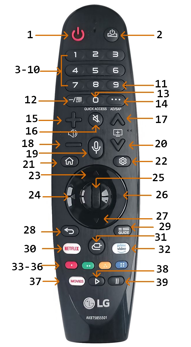
As testing the functioning of the DVR+ with this new universal remote requires a TV (well, duh!), I manually activated our LG TV controls into the INT-422-4 first. At least for this device I had existing operational remotes. The LG TV came with the LG “Magic” remote model AN-MR19BA. That LG remote controls a limited set of “most” TV functions like any standard IR remote, thus these few standard functions could by performed by any IR remote such as an INT-422. However its additional “Magic” features (e.g. the motion controlled cursor) communicate by RF signal on the 2.4 GHz Radio Frequency band, which a strictly IR remote cannot simulate.
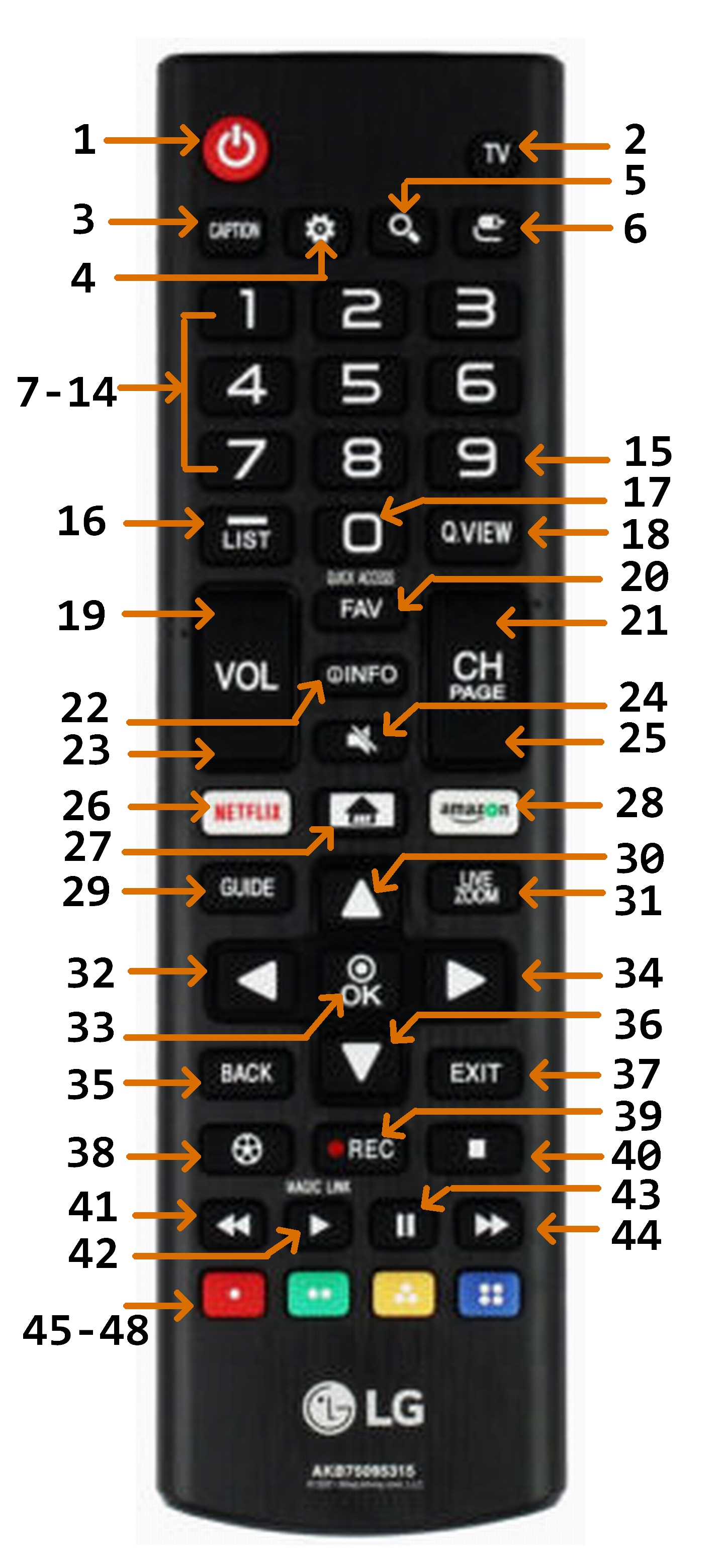
I had also purchased an LG “Standard” remote, model AKB75095315, from Amazon (https://www.amazon.com/dp/B09TD8FWY8) which is only an IR device. (Warning: There are several models of LG “Standard” remotes which somewhat differ in their key layout. These notes are for this specific model.) This “standard” remote has several more keys than the “Magic” remote so is the basis of my button names for the TV as related to the INT-422-4 universal remote.
This”standard” remote does make it “somewhat” possible to control the movement of a cursor function without RF by only using IR signals from various direction keys to “move” a visual cursor, but this is awkward and tedious. For the few cases where I really need cursor capabilites (such as when using the TV’s WebOS Internet browser) currently I choose to use either the original “Magic” remote with RF to control a cursor, or the more convenient touchpad on a Bluetooth keyboard I have paired with the TV via a USB dongle which also allows text input by typing.
This TV also has a “long press” feature for its OEM remote keys. Some keys have a built-in separate function which will be invoked if that key is held down for at least one second on either LG remote. As part of this feature the LG TV has a “Quick Access” function which can manually program direct invocation of an app or a live TV channel on a “long press” of (only) a Number key 1-9. A “long press” of the ‘0’ key invokes that “Quick Access” manual programming function. If the “long press” of any LG remote’s key was programmed for a separate function, whether built-in by system default or manually programmed using the “Quick Access” feature, a “long press” of an INT-422-4 remote’s button which is set to emulate that LG key will automatically also invoke that “long press” device’s function. I have used this feature on Number buttons 5 and 8 for frequent convenient direct access to the PBS channel and Amazon Prime app respectively.
IMPORTANT: Whether built-in by system default or manually programmed as a “Quick Access”, any INT-422-4 button assigned an LG TV key which has a “long press” will invoke that function, (but only) if the active Device Mode is set for the TV device even if the TV “input” is not currently set to the TV. Further it seems to matter the nature of the LG TV function invoked by the “long press”.
For example the “Mute” key on the LG TV remote also has a built-in “long press” function. Since all my devices route their sound through the LG TV which in turn has been set up to route its sound through my Sound Bar, I also use the INT-422-4’s standard “Global Volume Punch Thru” built-in Keypad Command mentioned above to have both its Volume controls (and Mute) for any Device Mode to be locked to (send the IR signal to) the TV. A “long press” of the Mute key on an LG TV’s remote will not perform a Mute of sound but instead will directly invoke the TV’s “Accessibility” Setup menu. NOTE: a “long press” of the locked INT-422-4 Mute key will always operate as if the remote is in the TV’s Device Mode regardless of the actual active Device Mode. Therefore when the INT-422-4’s Device Mode is not set to the TV, a “long press” of the locked INT-422-4 Mute key first will mute the sound but then also cause the TV’s “Accessibility” Setup menu to now display!! Since the active Device Mode is not currently set to the TV, any pressing of the INT-422-4’s navigation buttons will not affect that TV menu while still in that other mode thus preventing that menu from being used or dismissed. The active Device Mode must first be set to the TV, then use and dismiss that TV menu, then set the Device Mode back to what was previously active when the Mute key was long pressed.
Another example of confusion can be caused by a “long press” function on an ordinary unlocked INT-422-4 key when the active Device Mode is the TV but the TV’s “input” is not. If the invoked function will switch to a specific TV channel that “long press” will also switch the “input” to the TV, which is very helpful. But any other TV function (such as invoking an app) does not switch the “input” so that the screen does not show that the function has been invoked until the “input” is also changed to the TV. Similar to the example with the Mute key above, since the active Device Mode is the TV the remote’s buttons will be affecting the invoked TV function, but that action will not be seen since the TV is not the input.
[This potential for confusion exists whenever the electronic device linked to the remote’s active Device Mode does not match the device displaying as the TV’s “input”. To avoid this potential confusion is another reason I used the JP1 hardware and RM programs to program the remote. They allow the ability to be in any device mode and yet always switch both the Device Mode and the TV’s “input” to the same specific device by use of a specific fixed button for each device to ensure the input and mode stay in sync. I have not (yet) discovered how to generally create (or even override in the case of Mute) a “long press” function either manually or by standard RM programs.]
After activating the built-in 11840 Device Setup code for this TV on Device Mode button (A) my (necessary) experimentation found that most INT-422-4 buttons seemed to trigger a function appropriate to their labels. This built-in Device Setup code and the Global Volume Lock is only designed to provide the basic LG functions on an INT-422’s buttons. Since this LG model is a “Smart” TV with internet connections, one important function missing is access to that “Smart Hub” of features. On the LG remotes this access is provided by the “Home” key. The one-page How to Program the INT-422-3 for use with TV Smart Hubs which provides separate instructions to “add” access to that feature on that model remote also works for the INT-422-4 model and can be downloaded from the manufacturer: https://support.intesettech.com/forum/document-amp-video-library/int422-3-documents/48-int-422-programming-key-map-documents. This Smart Hub access is done by using the standard “Key Mover” built-in Keypad Command described above to override an INT-422’s DISPLAY button’s default function and directly assign the Advanced (EFC) function code to access the LG Smart Hub. [This LG “Home” key also has a preprogrammed “long press” function to list the Smart Hub’s “Recent Apps”. Testing confirms this “Key Move” also assigns this Smart Hub’s companion long press function to the INT-422 DISPLAY button.] Overriding this DISPLAY button’s built-in Device Setup default function does not seem to be a loss as that default function appears to duplicate the same function assigned by the built-in Device Setup code to an INT-422’s INFO button. The one-page Inteset instructions provide two possible LG (EFC) codes to accomplish this “Smart Hub” function (00516, 00683) and the first was successful. The DISPLAY button now accesses the TV's “Smart Hub” and “Recent Apps” functions (by short and long press), but only when the INT-422 Device Mode is set to the LG TV (A).
Finally, since the LG “Magic” remote has many fewer keys than the LG “Standard” remote, the table for that remote below only shows the TV’s functions controlled by this LG “Magic” remote’s keys without a comparison to an INT-422. That comparison, including any inclusion of “long press” functions, is shown with the LG “Standard” Remote table below.
The LG Magic Remote’s keys cause the functions shown in the following table as described by the OEM documents. As mentioned above some LG remote keys are preprogrammed or manually programmed with a “long press” function. The ‘#’ suffix in the table below indicates the built-in LG “long press” function which will be invoked if that key is held down for at least one second on either LG remote.
The model AKB75095315 LG “Standard” Remote’s keys cause the functions shown in the following table as described by the OEM’s documents. As mentioned above I activated the built-in 11840 Device Setup code for this TV on my INT-422-4’s Device Mode button (A), the additional 00516 EFC code to access the “Smart Hub” functions (by both short and long press) via a Key Move command onto the DISPLAY button, and also programmed the punch through command to lock the TV’s sound functions across all devices. My (necessary) experimentation now found that when Device (A) is active the function performed by the indicated LG Standard Remote’s key appears to be emulated by the INT-422-4 button shown in the table below. The listed 5 digit EFC codes associated with the function of the named LG keys were obtained from an electronic hardware update file on the JP1 site. While these EFC codes must be entered as five digits when doing a direct assignment of the function using the “Key Mover” Keypad Command, the table only lists the last three digits as the first two digits for all these LG codes are zeros. “KM” in the Device A button column indicates that this LG function has been assigned or modified for that button using a “Key Mover” Keypad Command as mentioned above. Those LG functions which are (apparently) Not Asssigned to the remote by the Device Setup code, are indicated by “N/A” as their INT-422-4 button number.
As mentioned above, some LG remote’s keys are programmed for a separate companion LG function by using a “long press” (held down for at least one second), whether built-in by system default, imposed by a manual Key Mover, or manually programmed as a “Quick Access” as I have done for some Number keys. If a “short press” LG function is assigned to an INT-422-4 remote’s button in the TV Device Setup mode, the companion “long press” LG function will also be assigned that button in that mode. These “long press” functions are indicated by the ‘#’ suffix in the table below. [See the above discussion of “long press” which includes concerns about possible confusions in invoking those LG TV functions with a “long press” of an INT-422-4 key when one or the other of the active Device Mode and the TV “input” are not set to the LG TV.]
Some of the identified LG functions did not appear to be assigned to a INT-422-4 button. In addition to the “Smart Hub” functions assigned by Key Move to the “Display” button described above, I also choose to use the Key Mover Keypad Command to directly assign these two EFC codes to the indicated buttons when in the TV mode. I prefer the LG’s more general “Back” function to the built-in Setup’s default “Last Channel” function. Further the INT-422-4 has no separate button for a “dash” or “period” for entry of a subchannel number so I use the Diamond button in the bottom row below the keypad. Finally although the Closed Captions can be toggled by first pressing the OK button and then while that display is on the screen pressing the Red button, I also assigned that direct function, which does exist on the OEM Standard remote, as a single button press to the Square button.
Finally, the following LG functions (plus some additional service codes) “apparently” have not been assigned to the INT-422-4 remote by the built-in 11840 Device Setup code. While their existence and (the last three digits of) their EFC codes are known [thanks to files on the JP1 Remotes Forum], in a few cases their functions are not clear to me.
Built-in Channel Master DVR+ Device Setup
The original “flat” remote that died for my Channel Master DVR+, model CM-7500XRC, is model “RRC9002-0102E A 05/11/13”. (As noted above there are other OEM remotes for this device.) I activated the first Inteset provided Device Setup code 04465 for Device Mode “B”, which also used the TV sound functions which had already been locked across all Device Modes.
My (necessary) experimentation found that when Device (B) is active some of the commands were different than expected or not assigned to a INT-422 button. I could simply use the standard “Key Mover” built-in Keypad Command described above to add or modify commands to this built-in Device Setup. However the Advanced (EFC) codes associated with an electronic device need to be known to use this feature. Fortunately most 5 digit EFC codes associated with the named DVR+ keys were able to be obtained from a post on the Channel Master DVR+ Owners thread here by senior user mdavej. Not all keys are listed as some functions (e.g. Volume, etc.) are intended to be controlled by the TV and not the DVR+. While any of these EFC codes must be entered as five digits when using the manual “Key Mover” Keypad Command, the table below only lists the last three digits as the first two digits for all these DVR+ codes are zeros as indicated by the heading. The following DVR+ functions which appear not be be assigned by the built-in Device Setup code I feel are essential to my convenient control of the DVR+. Thus when simply using the built-in 04465 Device Setup code I choose to use the above manual Key Mover Keypad Command to directly assign these EFC codes to the indicated buttons when in the DVR+ Device Mode. (Note that by testing I find that the posted Closed Captions EFC function code 00146 opens the audio menu which includes settings for that function, which is what is described for the “Audio/CC” button on the OEM peanut remote. However the documentation of my earlier OEM “flat” remote button #23 claims it “Toggles closed captions on/off”. As that OEM remote is no longer working I could not determine whether that was true and thus possibly discover a separate function code for toggle. Therefore I assigned the posted cc function (now on a macro?) to the EJECT button which is unused by the DVR+.)
For each DVR+ key and function in the table below, the button number under Device B indicates this DVR+ function appears to be assigned to that INT-422 button by the built-in 04465 Device Setup code. [The function names (if different) following the DVR+ key labels are from page 2 of the Channel Master Quick Start Guide.] Those DVR+ functions without an INT-422 button number are (apparently) Not Asssigned by the built-in Device Setup code, are listed below and indicated with “N/A” in the Device B button column. “KM” in the Device B button column indicates that this DVR+ function has been assigned or modified for that button using a “Key Mover” Keypad Command as mentioned above. Further some EFC codes although known for additional functions from the above sources were not even assigned to the DVR+ OEM remote. “N/A” in the DVR+ button number column indicates that function is Not Asssigned to a button on the DVR+ OEM remote.
Built-in ZVOX Soundbar Device Setup
The ZVOX Soundbar remote, model AV203, has very few controls which are primarily used to configure fixed settings. The OEM remote has only five buttons plus volume toggles. These settings seldom require change and this OEM remote is fully functioning, I did not activate its built-in Device Setup code in Device Mode ‘C’ for experimentation on the INT-422-4 remote. However I did obtain a Device Upgrade file for this device to potentially include with my complete RM programming of the INT-422-4 below.
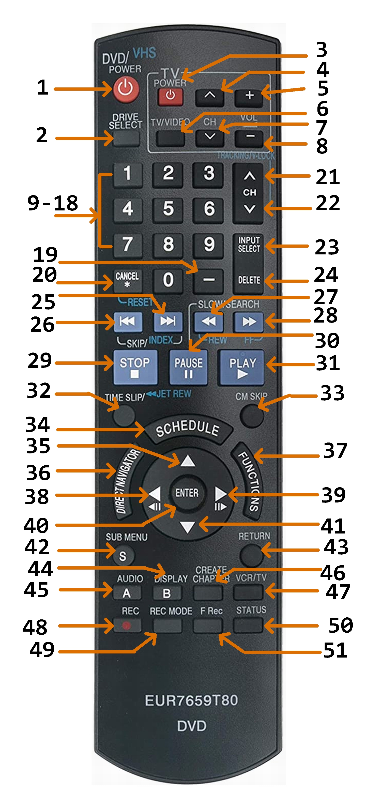
Built-in Panasonic DVD/VCR Device Setup
The Panasonic DVD/VCR, model DMR-EZ47V, came with the model EUR7659T80 remote. (As is also true for the DVR+, this device has other OEM remotes such as N2QAYB000136, but these notes are for my model.) I activated the first provided Device Setup code 21641 for Device Mode “D”, which also used the TV sound functions already locked across all Device Modes. My (necessary) experimentation now found that when Device (D) is active the function performed by the indicated DVD/VCR remote’s key appears to be emulated by at least some of the INT-422 buttons when the remote is assigned this built-in Device Setup code. However, not all the DVD/VCR remote’s keys were found by my experimentation to have a corresponding INT-422 button assigned by this built-in Setup code.
The 5-digit EFC codes listed in the table as associated with the function of the named DVD/VCR keys were obtained from an electronic hardware Device Update file on the JP1 site. (One function code apparently missing from this device is a direct code to access or toggle Closed Captions. That feature is only accessible through the “Other Functions/Settings” menu under Language.) The following few additional EFC codes and functions identified are apparently not assigned to a INT-422 button by the built-in Device Setup code.
Since the INT-422-4 remote’s has a button labeled “EJECT” I especially wanted the unassigned Open/Close function assigned to that button, and some of those other unassigned functions also might be useful assigned to a button. At this point I could have used the standard “Key Mover” manual Keypad Command to directly assign the Open/Close EFC function code (and any other unassigned functions) like I manually assigned some DVR+ functions. However several of the functions I normally used also seemed to be assigned to non-intuitive (to me) buttons. While I constantly view DVDs I now seldom use Video Cassettes, so those functions on this device were of little interest to me. Further unlike the DVR+ I had a working OEM remote so did not need to quickly get the INT-422-4 working for this device via a built-in Device Setup code. Most motivating was that I was now about to change to programming all button function assignments on the INT-422-4 via Device Upgrade files for all my devices and loading them by using the JP1 hardware and RM programs as described below. Therefore I curtailed any further experimentation of the built-in DVD/VCR Device Setup code without fully documenting its Setup’s default button assignments on the INT-422-4 remote.
The description of the remote in the included DVD/VCR Operating Instructions manual only numbers “groups” of buttons. Rather than using that numbering, for the sake of comparing my ultimate Device Upgrade button assignments with this OEM remote I separately numbered all its keys in the table below.
INT-422-4 Combined Built-in Commands
I began to build a table sorted by the INT-422-4 buttons to show what function each button would perform in each Device Mode based on the built-in commands. However, as I knew I was going to reprogram the remotes with JP1 hardware and RM software, and I had not fully documented the DVD button assignments, I decided to only build such a table for the final RM programmed remotes. However if I had not changed to JP1 and RM programming, I would have found it very useful to construct such a table as a print out to have with the remote.
Programming Device Commands
with RM software and JP1 hardware
on an INT-422-4 remote
Computer programs can be used to build a set of commands for a device which can be loaded by using a JP1 cable into a universal remote designed to control multiple electronic devices so that a given button will send an appropriate IR signal to cause a specific function to execute on a specific electronic device. To have access to all the necessary programs, help documents such as FAQs, and be able to post questions to JP1 experts, one must register an account with the on-line JP1 Remotes Forum http://www.hifi-remote.com/forums/index.php. Posts on that forum indicated the latest version of the complete open source suite of Java programs called “RemoteMaster for IR” is available from SourceForge at https://sourceforge.net/projects/controlremote/files/RemoteMaster/. I first downloaded and experimented with version v2.14.0. However later I updated to version v2.14.15 released June 6, 2022, which at the time of this writing is the latest official public version.
As part of this preparation I decided to be proactive and also identified and downloaded the four latest and most relevant RemoteMaster Device Upgrade (RMDU) files from the many Device Upgrade files in the File Section of the JP1 Remotes Forum for my four electronic devices: LG TV, Channel Master DVR+, Panasonic DVD, and ZVOX Soundbar. All the RMDU files I found for these devices were not specifically identified for my models but seemed to suggest they “fully” emulate the IR remote codes to send for all the functions for such devices which should control similar models of those brands of devices.
At this point I found it worthwhile to stop and spend some time reviewing the JP1 Wiki created to help understand both JP1 hardware connections and the latest version of the RemoteMaster programs: http://www.hifi-remote.com/wiki/index.php/JP1_-_Just_How_Easy_Is_It%3F. This “homework” was essential to begin to understand how to use all these programs and files.
It became clear that to upload device commands with custom RemoteMaster software one must use the hardware JP1 pin connections on the back of the INT-422 remotes. The DVR+ forum recommended I order an appropriate cable to connect to these JP1 pins. With that JP1 hardware cable and the RM software I was able to begin to explore this form of programming my INT-422-4 remotes.
My first attempt to install the downloaded RemoteMaster suite of programs via the included Windows setup program Setup.vbs on my Windows 10 computer complained that I did not have Java installed. [This is true Java, and not JavaScript often used in web pages.] So I downloaded what was the latest “Version 8 Update 333 (build 1.8.0_333-b02)” of the JRE from java.com and installed it. Now when I ran the RM setup program it complained of two things: my version of Java would not run within the latest Firefox browser which I prefer to use, and the version of Java was recognized as version 8 but needed to be at least version 15. The first was a known and accepted security issue, but the second was confusing as I cannot identify a version of Java later than 8, and even the appropriate Readme.html within the zip files of the version of the RM programs I downloaded specifies “Java version 8.0 or later”. However the setup ran to completion and the RemoteMaster suite of programs and files appears to be fully installed so I ignored that error message. I also placed a copy of the Start window’s shortcut to RMIR on my taskbar for convenience during testing and programming.
The latest Readme.html included with the latest version v2.14.15 of the RM programs gives a download location for JRE as http://java.sun.com/javase/downloads/index.jsp That file’s notes say either the Java Developer Kit (JDK) or the Java Runtime Environment (JRE) will be sufficient. This web page provided link to the JRE also points to a download of “Version 8 Update 333” which is what I originally found on the java.com site. This further reassured me I could ignore this error message.
Finally as Java applications by default have tiny font in Windows 10 on my high-resolution screen, it was essential to perform the following font change. These instructions are based on the JP1 Remotes Forum advice in the Beginners Forum posted by mdavej (a JP1 Forum expert member) in the topic “Change font size in RMIR”:
• Find the Java .exe file installed in Windows referenced by the RM Start shortcuts.
First check the folder where the Remote Master suite of programs was installed.
Right click any of the three RM program’s shortcut files (e.g. RMIR) and choose Properties.
The command entered in the Target field will start with the full path of a Java .exe file. For me it was C:\Program Files\Java\jre1.8.0_333\bin\
Go to that Java bin folder and select that specific .exe file. For me it is javaw.exe
• When in its folder right click on that Java .exe file and choose Properties.
Click on the button “Change high DPI scaling” towards the bottom.
In the new pop-up window check “Override high DPI scaling behavior”.
Below that set “Scaling performed by:” to “System”.
OK out of that pop-up window and the Java program Properties.
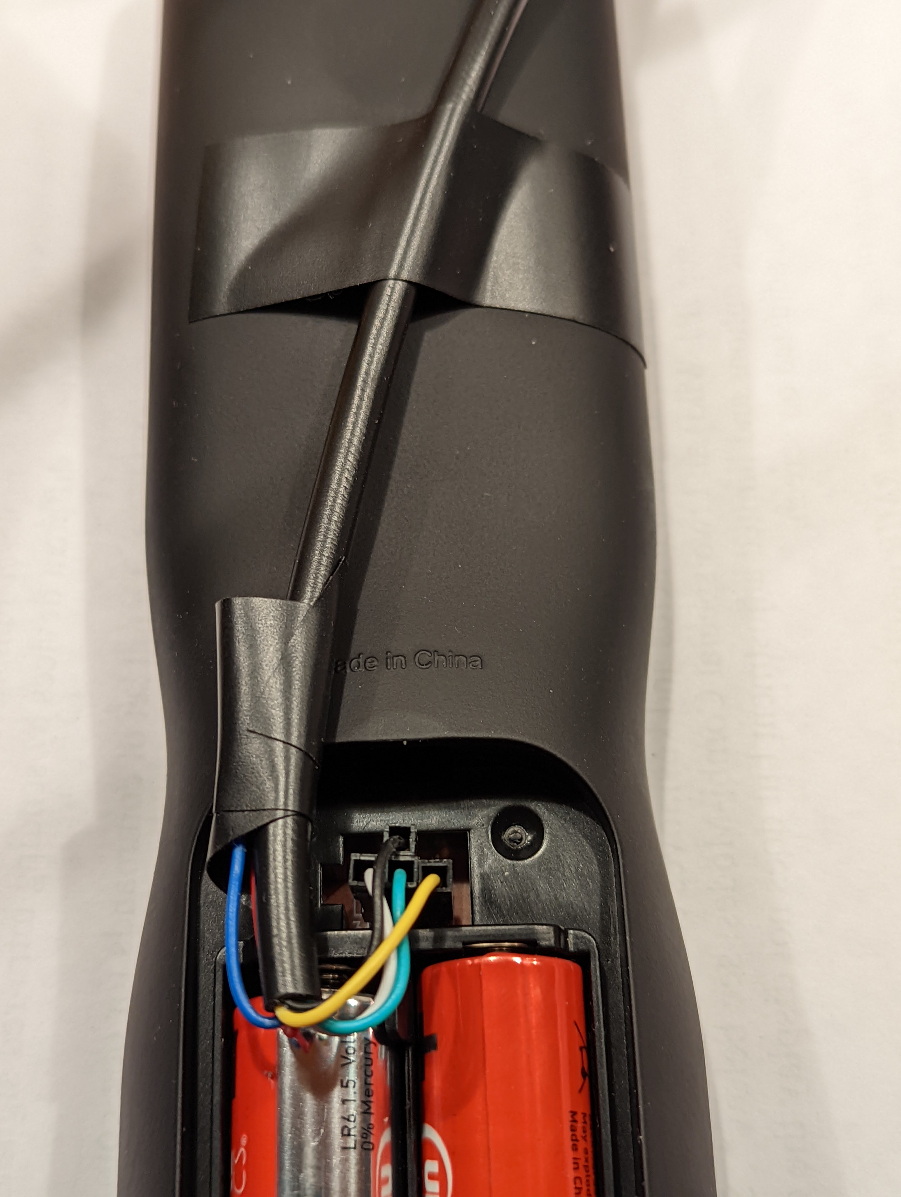
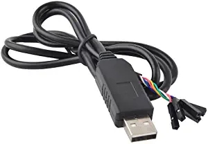 This “USB to TTL Serial Cable Adapter FTDI Chipset FT232 USB Cable” from DIYmall https://www.amazon.com/gp/product/B014GZTCC6 has six separate pin connectors on one end, each identified by the color of its wire, and a USB plug on the other. A vital piece of information from the JP1 site is that one cannot rely upon the wire colors to know which cable wire should connect to which JP1 pin on the remote. One must rely upon knowing the function of each of the cable’s wires to attach to the corresponding JP1 pin function. Next it is important to know that for these RemoteMaster programs one must NOT connect the cable wires for the functions CTS or 5V to the remote. There is even the special warning that connecting the 5V wire could damage the remote.
Connecting the INT-422-4 Remote to the Computer
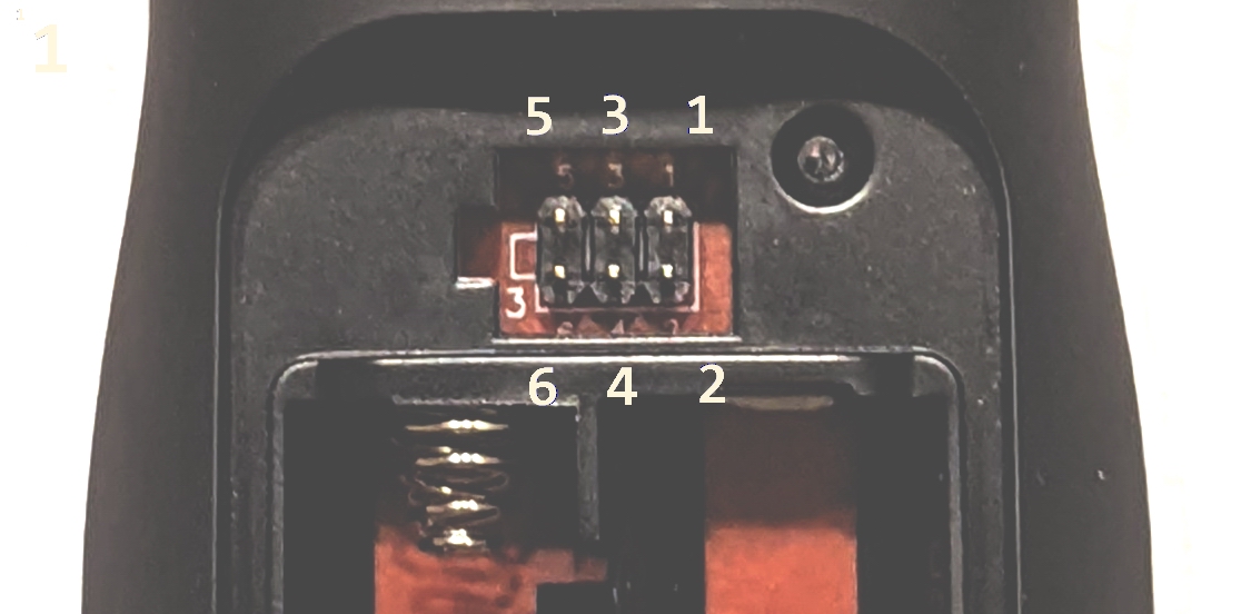
 As mentioned above I purchased two INT-422-4 remotes. (Ultimately one is for me and one for my spouse so we can have battles of the remotes. <grin>) One I immediately configured with manually programmed built-in Device Setup codes as the working remote as described above (since the original remote for the DVR+ was dead) and also manually assigned some Key Moves. The second remote I reserved for this JP1 programming experimentation. On the back of this INT-422-4, within the compartment and above the batteries, are the six JP1 pins. The pin numbers are printed on the circuit board next to where each pin is attached, but I added somewhat larger numbers to this picture to more easily identify the pin numbers.
As mentioned above before plugging the cable onto the pins one first needs to identify the functions associated with each of the colored wires of this particular cable, then identify the matching functions of each of this specific remote’s pins. Accessing both the cable’s and the remote’s manufacturer information produced the following tables which I used to connect this cable to this second remote. Some recommend glueing the cable’s separate plugs together in this configuration to facilitate any future plugging and unplugging required, but I didn’t expect to do that very often. Comments on both the DVR+ and JP1 Remotes Forums recommended that one connect the wires to the remote with batteries in place, and ONLY THEN plug (and unplug) the USB cable in the computer. Finally to ensure the wires do not come out while experimenting with this remote I taped the unused plugs out of the way and the entire cable to the back of the remote.
First encounter with the RM programs
To begin, follow the tutorial in the Readme.html file at the root level of the RM directory of this version of the programs created from the downloaded zip file. Use this instead of anything from on-line files (often with outdated instructions) as it will be the latest information and will most match this version of these downloaded programs. This tutorial web page also contains a link to the combined on-line tutorial of JP1 and the RMIR program mentioned in preparation for this programming activity. Further the Help menu within the RMIR program itself has direct links to both the included Readme and the on-line Tutorial.
With the cable connected to the appropriate pins on the remote I plugged it into the USB port of the computer and then started RMIR via the taskbar shortcut. As instructed, my first action was to (try to) download the existing codes within the remote into the program. This can be done either by clicking on the “Download from the attached remote” button (the middle button in the menu line of buttons), or clicking to open the “Remote” menu and choosing “Download from Remote”. While RM successfully communicated with the remote, it gave the Message “No RDF matches signature starting 3702”. This RMIR Download action is then aborted but RMIR remains running and connected to the remote.
RMIR electronically retrieved the internal hardware signature within the remote connected to the PC via the JP1 pins and cable. It then attempted to find a file within the installed RM folders with that exact internal signature. This warning message refers to files with a “.rdf” extension which are included with the RM installation in the separate RDF (Remote Device File) folder. This folder has .rdf files for a large number of remotes which each contain the internal details of that remote as needed for the RM programs. The program expects to find a filename beginning with the remote’s internal hardware signature. Unfortunately my model #INT-422-4 was too new a version of this manufacture’s remotes to have an appropriate file included in the zip file download. While I could do some separate experimentation with the RM programs without the remote to learn about these programs, I needed a matching .rdf file which had been constructed to define this new remote so I could program it using these programs.
This also seemed like a good time to learn about not only an .rdf file but all the files used by these RM programs.
It seems the contents of nearly all the various configuration files used by the RM programs are simply ASCII text. However the format of their contents is generally extremely structured and very precise, and their file “naming” is also often constrained and needing to be precise for the programs to automatically find them. Not only does each RM program expect specific filename extensions for its input files, but the program often will search for other associated configuration files based on a specific filename entered as a link within a loaded configuration file. The main file types used by the RM programs are listed below by their required filename extension:
This Remote Master configuration file built by the RMIR program combines all the commands which are required to upload complete sets of IR signals into the remote connected by JP1 cable to the PC. Set by the install script, by default Windows will automatically open these filetypes in the RMIR program. Such a file also can be opened by an ASCII text editor.
It references (but does not include within this file) the full definitions of a remote. This reference is done using entries of the specific remote’s name and its internal signature number which link to a separate .rdf file. The RMIR program will use further links in that .rdf file to also reference and access this remote’s .map and .jpg files to provide a graphical interface for assigning functions to its physical buttons as shown below.
[I feel sure there must be a way within RMIR to change what .rdf file is being referenced, but so far the only way I have found is by directly editing the .rmir file and changing the links. The .rdf file can itself be “edited” within RMIR using the magnifying glass menu button, but that does not allow assigning a different .rdf file to the .rmir file. TBD]
The specifications of a given electronic device’s functions to be controlled by this remote will either be obtained from a built-in Device Setup table preprogrammed by the remote’s manufacturer within the remote and accessed by its “Device Type” and “Setup Code” pair, or from a set of specifications known as a “Device Upgrade” copied into the .rmir file from a separate .rmdu file imported by the Remote Device Editor invoked from within the RMIR program. Built-in Device Type and Device Setup code values can be manually assigned to a remote’s Device Mode button for it to access by simply using the numeric buttons on the keypad as described above. That assignment can be observed in RMIR by download. Alternatively the Device Type and Device Setup code values can be programmatically entered in the RMIR program’s “General” tab for later upload into the remote. Further all electronic device specifications which have been copied into the .rmir file and are separately listed in RMIR on its “Devices” tab are available to be assigned to a Device Mode button. Commands within the RMIR program can only invoke the separate RMDU program to edit the specifications of a Device Upgrade which has been copied into the .rmir file. The specifications of a device which was manually assigned, either by a keypad code or by entering the two values in the RMIR “General” tab, is just a reference to a table of functions for that device built-in to the remote which cannot be edited.
This file defines a specific Remote Device. The install does not configure Windows to automatically open it in any of the RM programs, but it can be opened by an ASCII text editor. Its filename must begin with the exact number which is the remote’s complete internal hardware signature, e.g. 370201. As part of certain program actions RMIR will electronically retrieve the signature within a remote connected to the PC via the JP1 pins and cable and attempt to find a file with that signature in the “RDF Path” directory set under the “File” menu. (Otherwise RMIR will give a warning message as noted above when I first started.) Further that filename must have the formal “name” (brand and model) of the remote within parentheses following its signature number, e.g. “370201 (Inteset INT-422-4).rdf”. If a .rdf filename is included in an entry in the .rmir file, RMIR will automatically search for that file in the “RDF Path” directory. The search is based on the name in that entry within the .rmir file. If an exact name match is not found, it will provide a selection menu of either files which partially contain that name, or of all the files in that “RDF Path” directory.
The .rdf file’s contents (as described in more detail below) will also have an entry giving the name of this remote, e.g. “Name=Inteset INT-422-4” to display in the programs. As mentioned above it also contains a filename entry which is a link to a separate file containing map coordinates of the area of each physical button on an image of this remote, e.g. “ImageMap=INT-422-4.map”. While these RDF and Map filenames “can” be different than the “formal” name of the remote and from each other, they should match and all be unique enough to identify this specific model of this remote.
As described more fully below, this RDF file identifies all the physical buttons on this remote, their ButtonName text (both a name identifiable on this remote and if necessary a generic name), and their unique internal BtnCode values. It also identifies which of its buttons this remote designates as available (appropriate) to control each “Type” of electronic device, and the list of built-in Device Setup codes which this remote recognizes to access an internal device table for each of these Device Types.
This file identifies a set of areas where each physical button is located on an included image of this specific remote. The install does not configure Windows to open it automatically in any of the RM programs, but the free “Map This!” image map editor is often used to create these files. It also can be opened by an ASCII text editor. Its filename uniquely identifes this specific model of this remote, and must be entered in the remote’s .rdf file entry as shown above, e.g. “INT-422-4.map” as a link to this .map file. RMIR will automatically search for this .map file in the “Image Path” directory set under the “File” menu. This .map file’s contents will in turn have an entry linking to yet another companion file which is the image of this remote used to define the map areas. That image file’s basename must be identical to the basename of this map file, e.g. “INT-422-4.jpg” and is searched for in this same “Image Path” directory.
An area enclosing each button is defined by pixel map coordinates to that linked image which specify a covering shape. Each of these button areas is named in this map file with either that button’s ButtonName text or its BtnCode value from the .rdf file. Where a ButtonName in the .rdf file may contain spaces and some special characters including surrounding quotes, the area name in the .map file may not. In those cases the file format permits using the BtnCode value separated by a colon from a one-word description. The format is “$xx:text” with no internal spaces, where “$xx” is the BtnCode for that button from the RDF file, and “text” is a one-word comment which is typically an abbreviated name for that button. This alternative naming format will automatically retrieve the full ButtonName from the RDF file for the area name. The one-word comments are only viewable within the MAP file to make that button entry more human readable. I use this alternate format as it now allows a mapped button area to be labeled when viewed in the RMIR program the same more descriptive ButtonName which is allowed within the RDF file but not within the map file. See:“Map This - How To Create Maps for RM”.
This file contains the image of the remote which is expected and named by its companion identically basenamed .map file. I presume? formats other than .jpg might work, but that image format is the only format used for all the image files downloaded within the zip file of the RM programs. Like the .map file, RMIR will automatically search for the .jpg file in the directory “Image Path” set under the “File” menu. It should be of sufficient resolution to clearly distinguish each of the remote’s buttons so that each mapped button area can be distinct and clear, and the overall image generally sized to approximately 150x500 pixels so it fits in the area reserved for the image on the “Layout” tab of the RM Device Upgrade editor called from within RMIR.
This file contains the definitions of the overall functions of this one specific electronic device which can be controlled by IR signals as well as the button names used on the OEM remote for this device which are assigned to control these functions. Set by the install script, by default Windows will open this filetype in the separate RMDU (RemoteMaster Device Upgrade editor) program. Unlike some other RM configuration files neither the RMIR nor RMDU programs do automatic searching for this type of file. There are so many electronic devices which might be controlled by a remote that a set of such files is not included in the install zip file. However, an RMDU filename should be formatted for a human to easily find and identify a file for that specific electronic device in the extensive lists of downloadable .rmdu Device Upgrade files in the File Section of the JP1 Remotes Forum. By the JP1 site’s conventions the basename should begin with the Brand name followed by the exact model. If it is not obvious by the subsection where it is stored in the site’s File Section, the type of device could then follow in the basename, but nothing else, e.g. “LG OLED65C9PUA TV.rmdu”.
The separate RMDU program requires “some” remote to be identified to use in its graphical interface for assigning this file’s electronic device’s functions to buttons. Thus this file contains two entries identifying a remote’s name and signature number, e.g. “Remote.name=INT-422-4” and “Remote.signature=370201”. If an .rmdu file is directly opened in RDMU (such as by double clicking it in a Windows folder) the program will use those two entries to find that remote’s definition file in the “RDF Path” directory set in RMIR. It will also use that path to provide a drop-down list of the names of files defining all the remotes in that directory. RMDU will also use the “Image Path” set in RMIR to find the chosen RDF file’s companion Map and Image files. However, an RMDU file may be opened directly within RMIR by choosing to add a new device on the “Devices” tab. After finding and selecting an RMDU file via the pop-up Windows Explorer, RMIR will copy the Device Upgrade data in that RMDU file into the RMIR file and will override the link within this copy to any remote within that RMDU file with a link to the remote defined in this RMIR.
For further discussion of the contents of an RMDU file, especially the function and button naming conventions, see the section devoted to such files below.
Defining the new INT-422-4 Remote for RM
Without an RDF file which matches your specific remote model and its internal signature you cannot even begin to program and explore the possibilities of JP1 programming on this remote. There were .rdf files for earlier INT-422 models with different internal hardware signatures in the downloaded zip, but not for this specific new model. There is a separate subforum on the JP1 site called: “JP1 - New Remotes & RDFs”. Sometimes there may be posts in that subforum pointing to newly uploaded .rdf files for remotes not included in the programs’ download. However, searching did not find one for this specific new model.
There is also a “sticky” post in this subforum containing instructions of how to request a new .rdf file be developed. Among other things the instructions require uploading a “raw IR” file to the forum. This was obtained by running RMIR and under the “Remote” menu choosing “Raw download”. This action does not require an existing .rdf file. This menu choice opens a separate window where one clicks on its “Download” button. That action will propagate a table in RMIR with hex values. Now click the “Save” button, upload and post that file with its “.ir” extension to the “Diagnosis Area” of the forum File Section, and provide a link to the file in your post in the “New Remotes” forum which requests a new RDF file for this remote. That will (only) begin the process but demonstrates you are capable of connecting this new remote to the RMIR program.
After posting this initial required information be prepared to help in the creation of the definition file, as you are probably the only person currently on the forum with one of these remotes able to test. Rob “The Robman” (site owner of the JP1 Remotes Forum) sent me a message and provided access to an additional dump program: JP2Dumper. Running this with the remote connected produced yet another binary file which I uploaded for his use. After following his instructions for more actions with the remote and providing even more information requested by Rob, he finally was able to develop a new remote device file “370201 (Inteset INT-422-4).rdf” now available for download (as a “starter RDF” according to Rob) for others who might get one of these new remotes to use. [But (of course) as seen below I have “improved” <grin> this file for my own uses, and uploaded it for Rob and any one else.]
The internal details of the fixed structure of an RDF file is found in two documents, both available for download from the JP1 Remotes Forum in the “Tools/RDF Files” section of the JP1 File Section. These are “JP1 RDF File Specification Version 4” which is the baseline specification, and the “JP1 RDF File Specification Version 4 - Addendum” which documents the currently defined additions to Version 4 which update it to the new continuously being developed Version 5. The earlier RM program (IR.exe) only supports up through Version 4, where the current RM/RMIR suite of programs is intended to support the latest revision of Version 5. I have since learned from that documentation that my new model #INT-422-4 remote has features, such as “SegmentTypes”, which require the new Version 5 to access and use them.
The set of definitions about each given remote device is contained in its own separate specific .rdf file as described above. As indicated the RMIR software will retrieve the internal hardware signature of the remote connected by the JP1 hardware cable and pins to the PC, and then attempt to find a file with that signature in the directory “RDF Path” set under the RM program’s “File” menu. If found an .rdf file whose filename matches the remote’s internal signature code will automatically be loaded. All the RM programs use this file of the remote’s definitions to interact with this remote. As noted in the above paragraph the contents of most entries in an RDF file are not arbitrary and their format and contents are defined in the above identified specification documents. With few exceptions, their contents are intended to communicate to the RM programs exactly how this specific remote behaves, where and how it stores data, what complement of physical buttons it has, and so on. At this point in this chronicle about programming these remotes I choose to restrict my attention to button names as described below, and leave other RDF contents to Rob. Among other things I did learn that for the RM programs to recognize that the INT-422-4 could be programmed with Device Specific Macros, the .rdf file must contain the following entries:
Fortunately among all else in the “starter” file he created Rob did include these entries as I found I wished to use this new and somewhat “non-standard” feature.
Focusing on button names, the [General] section of the RDF file includes an “ImageMap” entry which provides a link to two other files described above: a .map file for this remote, and a companion .jpg image file of the remote. The RDF file includes up to three names in the entry for each of the remote’s buttons. As desribed above, the .map file contains only one name for the map area of each physical button, but that name must match either the ButtonName text or the BtnCode value of that button from the .rdf file. In addition to being defined in RDF’s [Buttons] section, a ButtonName may also be entered not only in the Map file but in other sections of this same RDF file. As of Version 5 the .rdf entry which defines each of this remote’s buttons can consist of up to three names in a specific sequence (where the first two can be optional as indicated by the square brackets):
[UEIName::][GenericName:]ButtonName=BtnCode
e.g. "Skip Forward"::"next track":SkipFwd=$21
Codes for a Shifted button (a BtnCode which is >$80) can also be separately specified in order to allow customized names to be given to shifted buttons. If any of these RDF names contains a space, and/or any of these five special characters “ ( ) , ; = ” the name must be enclosed in quotes, either single- or (preferred) double-quotes. However it is important to realize that names used in other places, like the RM files for the device buttons and multi-macro buttons [and Map areas], cannot be quoted, and therefore may not use spaces or any of these five special characters. The RDF Specification also suggests:
“…it is a good idea to use quotes on any name that contains characters other than letters or numbers, for future compatibility in the event the RDF specification is modified to use other characters for special purposes”.
By examination of some posted downloadable RDF files it also seems there is no harm in enclosing a name, even a single character, in quotes, even though it contains none of the restricted characters e.g.: "3":num_3=$28.
There are two reasons for prepending a separate, usually short, GenericName of a remote’s button in addition to having a normal ButtonName which is probably longer and/or more human identifiable on that particular remote. First RMDU files which define an electronic device generally come with their OEM function names which are likely able to be matched to a GenericName. However both the JP1 remote and the electronic device can have a ButtonName which is more identifiable on that specific remote or for that specific device. Thus any RMIR configuration entry containing a ButtonName concerning the remote (e.g. in the .map file) uses the name defined in the .rdf file for the remote, not the name concerning the electronic device in the RMDU file.
Most of the buttons on an OEM remote for electronic devices have common or “generic” names associated with the common or generic function they usually control. As a result the RM programs expect a button in an RDF file to indicate this generic function. A separate GenericName really should be specified in the RDF’s [Buttons] entry if the remote’s identifiable ButtonName text “does not match” a GenericName in the list below. This ensures the RM program can automatically match by default any RMDU generic electronic device’s function to an appropriate generic button on the RDF remote. The list below contains the 66 standardized GenericName values (shown quoted where required). As indicated in the RDF Specification, case is not significant for such a match but only the names in the list below are valid generic names.
The new Version 5 optional third name form UEIName described above indicates the default name for the function assigned to the button by a built-in Device Setup code. This is needed only for UEI remotes that create a remote Device Upgrade corresponding to each assigned device button but without names for the functions so assigned. Typically this UEIName is a human-readable expanded version of the button name as in the example above.
First Views of the RMIR Program
With an appropriate .rdf file I could now run the RMIR program and begin to get an idea of how this program works and what it does. I began by investigating the .rdf file from within RMIR. Then I copied in some of the RMDU files I had downloaded as part of preparing to do JP1 programming, and analyzed them within RMIR as well as their impact on the master .rmir configuration file. Next I explored the equivalent way to implement the functionality which I had done with the manually entered Keypad Commands which were needed to add some unassigned functions to the built-in Device Setups for some electronic devices.
OEM supplied remote’s view in RMIR
With an appropriate .rdf file I could now run the RMIR program which (now) automatically loaded Rob’s matching “starter” RDF file based on its internal hardware Signature number (370201). This permitted me to begin to understand how to customize this remote. As I mentioned above, before trying the RM programs I manually modified one remote by assigning some built-in Device Setup codes for my electronic devices as described above. Fortunately I had not modified the second remote. Thus I could download and analyze that unmodified remote.
As directed in the Readme, I began by downloading the data from the remote into the RMIR program which automatically loaded the (now available) matching startup RDF file based on the remote device’s internal hardware Signature number which the program retrieved as indicated below. By downloading the data rather than opening an existing .rmir file, RMIR automatically builds a new .rmir file from this downloaded data. It is a good idea to save this file as a way to return the remote to the OEM delivered state if needed.
The first information of these factory defaults is displayed on the “General” tab. This data shows the four factory preset built-in Device Setup codes preassigned to the four Device Mode buttons. These are the codes of 02615 (Apple TV) as device 2 on A, 03061 (Roku) as device 4 on D, 01272 (MCE) as device 5 on C, and 04000 (Xbox One) as device 6 on B, with no programmed Volume or Channel Punchthrough controls set.
In this OEM shipped state, all the tabs “Key Moves”, “Macros”, “Global Punchthru”, “Special Functions”, and “Learned Signals” entries are empty.
This first view of the “Devices” tab for the OEM supplied remote shows a list of additional Device Setup codes. By opening the RMIR file of this state in an ASCII editor it became clear that these are other electronic devices with full Device Upgrade entries now copied within the RMIR file. While there are many “Built-in” Device Upgrade definitions hard coded in the firmware of the remote, these Device Upgrades were stored in the programmable memory of the remote (likely because they were too new to have been built into the hardware so are made available this way). As a result these can be viewed in RMDU and edited if desired. However the only information this Inteset data provides is the various function names, codes, and default button assignments, with no identificaton of the actual electronic device being controlled. [Left as a later academic exercise to identify these electronic devices.]
Finally the “Raw Data” tab shows data internal to the remote which was retrieved by the program. [The details of this data is more advanced than I wish to explore at the moment]. However the hardware details of this model remote shown on that tab, which includes the retrieved hardware signature, are of interest:
As a later experiment I reset one of the remotes to Factory Defaults by the Keypad command ‘977’ to get an idea of what that produces. This download was identical to the information above except the “Devices” tab was now empty and thus there were no additional Device Upgrade definitions in the RMIR file created by the download. This reinforced my assumption that Inteset had stored those additional upgrades in programmable memory which is overwritten by RMIR since they were now not accessible.
After Built-in Device Setup view in RMIR
As mentioned above I manually modified one remote by activating some built-in Device Setup codes for my electronic devices as described above. This included the Device Setup codes for three of my four devices, as well as a Global Volume Lock to the TV, and the TV’s Smart Hub function code. After having reviewed the OEM supplied state I performed those same manual actions on my test remote. I then downloaded the data from the remote into the RMIR program to see what RMIR file this download would create.
The first information is again from the “General” tab. This data shows the built-in Device Setup Codes which I manually activated in place of the preset Setup Codes on the Device Modes A, B, and D. It also shows my manual programming of the Punchthrough Global Volume control from button ‘A’ (the TV) on device #2.
Next the “Key Moves” tab shows any of these kinds of assignments to specific buttons. From this download that tab shows the results of my manual assignments with the “Key Mover” built-in Keypad Commands as were described above for the TV and DVR+. As Key Moves may also be programmatically set within the RMIR program on this tab, I discuss them in more detail (which includes the view of the full table created from this download as an example) in that separate programmig section below.
With the functions manually set by these basic codes and Key Moves, the other tabs “Macros”, “Global Punchthru”, “Special Functions”, and “Learned Signals” are empty. But it shows that the additional OEM pre-defined devices in the remote’s memory in the “Devices” tab are still available and unchanged by just doing these manual override assignments.
I was disappointed to discover that after activating these built-in Device Setup codes the RMIR program does not have access to what functions for that electronic device are set on which buttons of the INT-422-4 when that mode is active. However as stated in the JP1 Wiki “In most cases, the JP1 tools can't be used to extract any of the built-in setup code details”. Thus I was required to experiment to try to discover the button mapping for each built-in Device Setup code in order to later compare with the mapping available or created in an RMDU file for that electronic device.
The INT-422-4 Remote’s Buttons in RMDU
The RM programs, which construct the master .rmir file uploadable to the remote, make every effort to make it easy to identify the association between the physical buttons on a particular remote and the one or more functions invoked by the IR code(s) sent to an electronic device by pressing that button. However, the RM programs also can assign functions to “keys” which do not have any relationship to physical buttons on a given remote. These are generally called “phantom” keys as they are not associated with any physical buttons. This is a powerful feature only available when programming a remote, especially useful for defining RMIR macros.
The button information displayed by the RM programs is based on the separate .rdf Remote Definition file for that remote which not only defines what physical buttons are on this remote and their names, but also references an image file which displays this remote’s buttons. The function information displayed by the RM programs is based on the separate electronic Device Setup code for each electronic device, which either refers to a built-in table of functions for that device within the remote, or refers to a separate “Device Upgrade” table of functions for that device within the .rmir file, probably copied from an .rmdu file. RM programs combine access to all this data about the remote and the devices from multiple files to visually display the associations between buttons and functions and then upload all the defined commands to the remote.
The “General” tab in the RMIR program displays the electronic Device Setup codes currently assigned in the RMIR file to each Device Mode button of this remote. If a Device Mode button is assigned a built-in Device Setup code the internal programming in the hardware of the remote knows what IR function code(s) to send from each button when that Device Mode is active. But as mentioned above RMIR by itself does not have a way to show those built-in function codes and button mappings. It can only show what built-in Device Setup is assigned to that Device Mode button. However any Device Setup code listed on the separate RMIR “Devices” tab (some of which might also be assigned to a Device Mode button) has a complete table of functions for that device within the .rmir file which RMIR can use to invoke the companion RMDU program to visually display the functions, their RF codes, and the button mappings on this remote for that electronic device.
First RMDU Remote Buttons view
In addition to the Device Setup codes assigned to the Device Mode buttons, the initial Download from this INT-422-4 into the RMIR program also shows a sizable list of Device Setup codes on the “Devices” tab. As mentioned above any built-in codes assigned to a Device Mode on the “General” tab cannot be edited to show their table of functions or their button mappings. However any entry in this separate electronic “Devices” tab can be highlighted and Edited in the automatically invoked separate Device Upgrade program (RMDU) to get an idea of what mapping of these functions to the remote defined by the .rdf file “could be” available. These extra Device Upgrades are in tables pre-loaded in the INT-422-4 internal memory which can be downloaded by the RM programs. Unfortunately they only contain their function names and codes and the default button assignments, but do not identify the electronic device which they are designed to control. [Left as a later academic exercise to identify the electronic devices for these pre-loaded but accessible tables.]
However by selecting any one of these extra Device Upgrades and chosing Edit, the RMDU Device Upgrade Editor opens which can use its upgrade table downloaded into the .rmir file as an example to show that electronic device’s functions and their mapping to buttons or keys on this remote. Since at this point I was most interested in how well the “Starter” .rdf and .map files (based on the earlier INT-422-2 model) defined the INT-422-4 remote’s physical buttons (whatever the assigned functions for some device), such an example was sufficient for this initial exploration.
While the RMDU “Functions” Tab lists all functions and codes for this electronic device which “could be” assigned to a button or key, the “Layout” tab is the most visually obvious for showing the current button mapping to this remote as it includes a complete image of this remote showing all its buttons with separate mapped areas of each button. This tab also contains a table with separate table cells for every electronic function for that device defined in the Device Upgrade, where any function not assigned to a button or key is in red.
By selecting a Mode on the Layout tab of either Normal or Shifted, the remote’s image displays the area (defined in the .map file) of a button or key. That area is colored in bright yellow if it has been assigned a function for this electronic device in that Mode. All buttons or keys which are listed in this Device Upgrade table are edged in orange.
The round extra “buttons” below the remote’s image are those “keys” which are named and assigned a button code in this remote’s .rdf file but are not identified as a physical button in the companion .map file. These are generally the so-called “phantom” keys as they are not associated with any physical buttons. They are primarily used as a “place holder” for a function which is not otherwise assigned to any physical button but is intended to be invoked in some way. Since a phantom “key” can be used in a Key Move or included within a macro’s sequence of “button” presses, these keys provide a way to invoke functions which do not need to be assigned to (and use up) a physical button. [For an example of their use to facilitate my remote switching between Device Modes see below.]
When working in this “Layout” tab, clicking on a button or key will select it and will now show it enclosed in a white border. To assign a function on this selected button/key (or change its assignment to a different function), either right-click on this selected item to pop-up a menu of all defined functions and select a function, or alternatively double-click a function in the table of Available Functions to assign that function to the selected button. Hovering the cursor over any button/key will show its name as defined in the .rdf file, then followed by an equals sign and the electronic device’s function name if one is assigned.
The “Buttons” tab is essentially equivalent to the “Layout” tab described above but without the visual image of the remote. It contains a table with rows of the defined names of all the remote’s buttons and phantom keys in the first column, with the electronic device function assigned to that button/key, normal and/or shifted, in the next columns. If a button or key has no function assigned, its name is in red. Like the “Layout” tab if a function in the equivalent Available Functions table has not been assigned to a button or key that unassigned function name is in red. While this version of the RM programs’ “ReadMe” claims there are other methods, in this version of the program the only way I could find to assign (or change) a function to an un-shifted button or key on this tab is to drag-and-drop the desired function from the Available Functions table onto the table cell into the normal Function column for that button/key. However selecting a shifted table cell then pressing Escape will pop-up a menu of all functions to select a function for that selected shifted button/key, similar to the “Layout” tab’s pop-up menu.
The official RDF Specification states that the physical button names in the [Buttons] section of a .rdf file “may be entered in any order, with the order possibly having an effect on where it will show up on the list of buttons within programs.” However I believe this may not be true based on the information about the RDF’s [ButtonMaps] sections. There are multiple [ButtonMaps] sections within the RDF, generally one section for each Electronic Device Type which begins with the digit for that type of device (e.g. TV=1). This is then followed by the internal BtnCode keycode values of only the buttons which this remote considers appropriate/usable and thus available for this device type. If appropriate for this device type the numeric buttons keycodes always come first and are grouped in parentheses as a single entity in the numeric order of their buttons (0, 1, 2, 3, 4, 5, 6, 7, 8, 9). Then if appropriate always come the three volume control buttons (volume up, volume down, mute) grouped in parentheses, followed by the keycodes of the two channel control buttons (channel up, channel down) grouped in parentheses. Finally only those remaining buttons which are considered appropriate/usable and thus available for this device type now follow in this device type section. Thus only these buttons listed in the ]ButtonMaps] section may be used as physical buttons on this remote within a Device Upgrade identified as this device type.
It seems RM first scans through the multiple [ButtonMaps] sections within the RDF looking for the longest [ButtonMaps] section (i.e. the one with the largest number of usable buttons, usually for device type 0=CBL/SAT). It places the names of the buttons whose keycodes are in that longest [ButtonMaps] section first within the [Buttons] section (in the same order as in that device type’s ButtonMap). It then adds all the names of any remaining buttons whose keycodes are not in that longest [ButtonMaps] section in the order they are found in a [ButtonMaps] section. Multiple posts on the JP1 Remotes Forum declare that the nature and order of these [ButtonMaps] sections are internally hard-coded within the specific remote and should not be modified in this file. Thus it seems the resulting order of the button names in the [Buttons] section might also be (somewhat?) fixed due to them being based on the fixed order of their keycodes in these [ButtonMaps] sections. The [Buttons] and [ButtonMaps] sections are a few of the many aspects concerning creating an RDF file for a new remote which I leave to the experts, as it appears much of this information must be retrieved from within the internal memory of the remote itself.
As mentioned above, the [General] section of the RDF file includes an “ImageMap” entry which defines a .map file for this remote, and by definition a companion identically named .jpg image file of the remote. A large number of pairs of such files come in the separate Images folder within the download of the zip file which also contains the RM programs. A pair of companion files will have the remote’s name as their identical filenames, differing only in their file extensions. The .jpg image file which Rob referenced in the “Starter” INT-422-4 RDF file was of an earlier model and not “quite” what this new model #INT-422-4 looks like. It was easy to create a new .jpg image and name it with the new remote’s model number and upload it (and create and upload a new companion .map file) to the Forum.
As also mentioned concerning button naming, a button area used in the .map file either must be identified by the ButtonName or the BtnCode in this remote’s .rdf file which links to this map. However, a ButtonName in the .map file cannot contain spaces, special characters, or even quotes. The .rdf file’s ButtonName is typically chosen to be the identification of the button’s area in the .map file. However that ButtonName may include some of these characters, possibly to indicate multiple functions invoked by this button. Further the .rdf file’s ButtonName may need to be enclosed in quotes for other reasons. Since such a ButtonName cannot be used as an identifier in the .map file, some shortened “legal” name “could” be used. However the BtnCode from the .rdf file can be used instead as the button area’s identifier, which I believe is a better option. That BtnCode is then followed by a colon and short text (with no spaces or special characters) to identify this button area to the human reader of the .map file. For example the ButtonName entry in the .rdf file for the numeral two button is:
Since this "2 / abc" name in the .rdf file contains characters, including quotes, prohibited in a .map file ButtonName, the map entry identifier for that button area in my .map file uses its BtnCode:
Using the BtnCode of $27 as the .map identifier of the button area instead of some shorter but possibly cryptic “legal” name will allow the button to (also) display the full .rdf file’s text “2 / abc” (without the quotes) for that remote’s button label in the RM programs, which I prefer.
While the names which Rob assigned in the “Starter” RDF and map files were identifiable, these names do not “quite” match the Inteset button names in the documentation for an INT-422 remote downloadable from the manufacturer: https://support.intesettech.com/forum/document-amp-video-library/int422-3-documents/48-int-422-programming-key-map-documents. Since I generally choose to use the full OEM name or the label on the button, either of which may contain special characters, I made ButtonName changes in both the “Starter” RDF file and the linked Map file (both of which I then uploaded to the Forum as mentioned above).
Any GenericName value in the table below indicates no match of the desired ButtonName to a standard generic name, and that value will precede the ButtonName in the compound RDF name as shown in the example above for the “2” button. Finally the identifier of the area of this button in the separate .map file (either the ButtonName or the BtnCode:text link) is shown in the final column.
A Device Upgrade, whether built-in to the remote or copied into the RMIR file from an RMDU file, defines the default action of a button when in that Device Mode. Manual Key Moves described above are a powerful capability of many remotes, but are especially powerful when using the RM programs with a universal remote. As mentioned above concerning the standard hierarchy of button overrides on a UEI remote, assigning a Key Move to a button will override (but not overwrite) the default function and any Device Independent Macro assigned that button. However as also mentioned above, the Inteset OEM documentation states a Key Move on an INT-422 will overwrite (not override) any Device Specific Macro (but not the default function) assigned that button. As described for manual override assignments, a given model remote may restrict which buttons may be assigned Key Moves. As noted in the overall description of manually overriding the action of a button, although the documentation of all prior models of the INT-422 mention Key Moves, neither the INT422-3 Technical Document nor the latest model INT-422-4 User’s Guide mention how to assign a “Key Move”. However my testing shows that the INT-422-4 remote does accept these, both manually and by RM programming.
An RM programmed Key Move like its manual counterpart involves a single key or button when a single Device Mode is active being assigned one device/function pair where that function controls its single (possibly different) paired electronic device. The RMIR program has the separate “Key Moves” tab to both set and display this feature. An early download of my remote’s settings shows the results in that tab of manually setting these overrides with the “Key Mover” built-in Keypad Command as were described above for the TV and DVR+. In these below few manual examples since they were simply assigning functions which the built-in setup had not assigned, both the assigned Device Button mode of the assigned Key and the Source Device Type/Setup Code of the assigned Function are associated with the same device. Further the Device Setup codes for these example Device Upgrades are all built-in.
For each defined Key Move the columns in the table on the “Key Moves” tab in RMIR show:
• the Device mode of the remote which must be active to invoke this Key Move function identified by the “Device Button” assigned that mode.
• the specific key or button which will invoke this Key Move function when pressed in the “Device Button” mode paired to this companion “Key”.
• the electronic device which is the source of this controlling Key Move function identified by the pair of values in the “Device Type” and “Setup Code” columns. Often this source device to be controlled is different than the Device Mode which must be active when pressing the assigned key.
• the function to be invoked to control this “Device Type/Setup Code” source device. Its identifying value is from this device’s table of functions shown in three equivalent ways: “Raw Data”, “Hex”, and finally either the EFC-5 five-digit code or the name of a key or function defined in this source device’s table of functions. In the above examples the table is showing the EFC-5 codes which were entered by the manual Key Mover command using the remote’s numeric keypad and then downloaded to RMIR. Now RMIR automatically displays their equivalent two other values.
Normal RM Assignment of a Function to a Button
Most buttons of a remote are assigned default functions when a given Device Mode is active based on the Device Upgrade for that mode identified by its “Device Type” and “Setup Code”. As mentioned repeatedly this Device Upgrade may either be built-in or a complete Device Upgrade contained within the .rmir file.
If the upgrade is contained within the .rmir file, any of that device’s functions can be directly assigned as default to the desired remote button within that upgrade without need of a Key Move simply by editing the device’s upgrade as described below.
If the upgrade is not already within the .rmir file, a complete upgrade file for that or similar device usually can be found among the many Device Upgrade files in the File Section of the JP1 Remotes Forum. It can then be downloaded, accessed by the RM programs, edited as desired, and copied into the .rmir file. If one is already going to the effort to use the JP1 hardware and RM software to be able to upload device settings to the remote, then I believe finding, editing and loading a complete Device Upgrade is well worth the effort. The Device Upgrade Editor's visual interface makes directly assigning a device function as default to a remote’s button when in that Device Mode much easier and more intuitive than Key Move assignments.
However if a (near) complete Device Upgrade file cannot be found, or even for some special function assignments mentioned below, a Key Move may need to be assigned within the RMIR program. In my opinion using a Key Move within the RM programs to assign a function as default on a remote’s physical button involving the same device and mode (for both source and destination) is only required when the Device Upgrade is built-in and you cannot (or don’t wish to) find a .rmdu file for that electronic device. However assigning a Key Move within the RM programs is always required (whether involving both the same or different device and mode) whenever the electronic device's function needs to be assigned to a key which is not a physical button (i.e. a phantom key). The only way I know to accomplish a phantom key assignment is by an RMIR programmed Key Move. (Am I missing something?)
An extremely useful feature is that a Key Move can assign a key or button which is operating when one Device Mode (the destination) is active to execute a function which is defined in a different Device Mode (the source). Because the assignment and the function can both be specific to a Device Mode, multiple Key Moves could assign the same (destination) key or button completely different (source) functions for each different active (destination) mode. A significant way to take advantage of this feature is when one couples Key Moves with Macros. Whether programmed manually or by RMIR, a Macro is only assigned a sequence of keys or buttons (not functions). A Device Mode independent Macro could include in its sequence a key or button where the (source) functions assigned those keys/buttons actually depended upon the (destination) Device Mode currently active due to being a Key Move assignment. Thus even though the Macro’s button presses are Device Mode independent, the sequence of functions they will perform might not be. For an example of such a coupling see the Key Moves associated with my Switch Device Functions example.
When in the “Key Moves” tab clicking “New” (or Edit) pops-up a separate “Key Move” window where you can specify (or modify) all the information for this one Key Move. First the (destination) “Bound Key” device/key pair to which the function is to be assigned is identified by selecting from the pull down menus both the (destination) Device Mode button and the button or key to be assigned that function when in that mode, and checking whether the function is to be invoked with that key shifted:
Next the (source) “Function to Perform” is identified by first specifying the associated (source) Device Mode button, and then its actual function. The two Device Mode button lists displayed in this tab for both the source and destination are essentially identical to the list in the table of assigned modes on the “General” tab. Double clicking anywhere on one of the (source) Device Button full rows will automatically fill in the Device Type and Setup Code boxes at the bottom of this section. Otherwise a (source) Device Type must be selected from the pull down menu and a Setup Code manually entered.
If the Device Type and Setup Code is not known to this .rmir file (neither built-in nor from an included Device Upgrade) the actual function code for that (source) Device/Setup itself must be specified in one of three ways.
If “EFC-5” or “Hex” is checked, enter the five digit code or single hex value of the function in the entry box provided as shown above. If “Key” is checked a drop-down menu will replace the entry box to list all function keys which this remote considers available for this Device Type for a selection.
More common is when a Device Type with a Device Update known to this .rmir file is selected. Then the “Function” option can be chosen so that a drop-down menu will replace the entry box at the end of the line to list all the functions from this Device Update table for a selection.
An example of a completed table on the “Key Moves” tab is my switch device functions mentioned above after programming three separate Key Moves to the single created TVInput phantom key to assign three different functions when in three different modes.
Programmed Key Move assignments are only stored as part of the .rmir file. These assignments do not affect any of the separate .rmdu Device Upgrade files or the separate .rdf remote definition files. They must be included within the .rmir file as such an assignment needs to know about both the device having the function and the Device Mode on this remote to which the key is assigned. Only the .rmir file has all this combined information.
As repeatedly mentioned a Device Upgrade, whether built-in to the remote or copied into the RMIR file from an RMDU file, only defines the basic functions for an electronic device, such as the default action of a button when in that Device Mode. Macros are an additional powerful capability of many remotes to control electronic devices, especially when using the RM programs with a universal remote. Depending upon the remote, a macro assigned to a button can be a Device Independent Macro (DIM) or possibly a Device Specific Macro (DSM). As noted in the above table of manually programmed commands, the INT-422-4 allows using the remote’s keypad to program both types of macros. However I learned that the fact that the INT-422-4 is capable of recognizing the special protocol of a DSM must be included in the .rdf file which describes this remote to the RM programs. Emphasizing that DIM and DSM are two different types of macros, the RMIR program has separate tabs to define and display each type on the remote. Since the macros may involve multiple electronic devices, just like Key Moves above both types of macros are stored as part of the .rmir file as only it has such combined information. They are each identified within the RMIR file as a separate [KeyMoveEFC5] section.
One important feature of macros is that they do not loop, they are not recursive. As mentioned when describing the UEI standard hierarchy of assignments which can override the default action of a button, assigning a Macro to a button can override (but will not overwrite) its (lower) default function. This means that if a macro is assigned to button XYZ, that macro’s sequence of button presses can include this same button XYZ. Although manually pressing the button now invokes the assigned macro, since the default function is still assigned that button, the keypress of that button included within that same button’s macro now will invoke its default function not the macro.
[It appears? that any button/key in a macro sequence which is assigned a macro will always instead invoke the (lower) default function of that button/key. While this now allows access to that default function in that button’s macro, this also seems to prevent “nested macros”, i.e. a macro which invokes other macros. I have not further tested or explored this issue. However notes on the JP1 Remotes Forum suggest nested macros are usually accomplished with a special “extender” program as part of the RM programs, but it appears such a program does not (yet) exist for the INT-422-4 remote which apparently uses a new JP1.4 hardware interface. I could see desiring to assign a multi-use macro to a “phantom” key and then include that key’s press within multiple other macros, but I have not tested this and expect it to fail.]
Like Key Moves, the manufacturer of a given remote may restrict which buttons may be assigned Macros, and some remotes even have buttons which may only be assigned Macros. As mentioned when manually assigning a macro, the INT422-3 Technical Document states that all keys except the SET key (including the Device Mode buttons) are available for a Device Mode independent macro (DIM) to be assigned, and its macro sequence can be up to 32 button/key presses. A Device specific mode dependent macro (DSM) cannot be assigned to either the SET key or any Device Mode key.
Manually assigned macros must be defined as a sequence of only (unshifted) physical “button” presses. However an RMIR programmed macro sequence can include additional entites, such as shifted button presses described below and “phantom” keys. As mentioned above the RM programs can define entities called “keys” which also can be assigned device functions. These are generally called “phantom” keys as they are not associated with any physical buttons. They are primarily used as a “place holder” for some assigned function which is (intentionally) not assigned to any physical button. Most importantly these phantom “keys” also can be included in a programmed macro’s sequence of “button” presses. Thus this programmable “key” feature allows invoking functions within a macro which are not assigned to (and use up) a physical button. This provides a powerful expansion beyond manual assignment of a macro.
Most modern remotes accept programming of the DIM type of macro. The assignment of a DIM, often called a Global Macro, overrides the default function of a button in all Device Modes. Thus whatever Device Mode is active, pressing the button assigned that macro will cause that sequence of button (or key) presses to execute and thereby invoke whatever functions are assigned those keys or buttons in the then active mode. The DIMs are defined and displayed in the separate “Macros” tab of the RMIR program. They are each identified within the RMIR file as a separate [Macro] section.
Only some modern remotes also accept programming of the special protocol of a DSM. As noted above the INT-422-4 accepts both types of macros. The assignment of a DSM, each identified within the RMIR file as a separate [DSMFunction] section and requiring special entries in the .rdf file of the remote to recognize them, overrides the default function of a button in only one Device Mode. Thus only when that Device Mode is active, pressing the button assigned that macro will cause that sequence of button (or key) presses to execute and thereby invoke whatever functions are assigned those keys or buttons in the then active mode. DSMs are defined and displayed in the separate “Special Functions” tab of the RMIR program.
As mentioned above concerning overriding the default action of a button, assigning a Key Move to a button can override both its default function and any Macro of either type assigned that button. If a particular manufacturer’s remote only allows DIMs, a DSM can be “simulated” by assigning a DIM to a button for every mode, and then doing a Key Move to assign a function (even the original default function) to that button to override the macro for each Device Mode where the Macro is not desired.
Finally, since a macro is a sequence of button/key presses, one of those buttons can be a “change Device Mode” button. If included in the sequence of button presses it will change the active Device Mode. As a result the subsequent button presses within the sequence will now operate in that mode and invoke the function for that button in that (possibly different) mode. The remote will remain in the last mode made active by the macro which may not be the mode active when the macro was invoked, which could be part of the purpose of that macro.
However note that assigning a DIM macro to the mode keys themselves can produce difficulties. As the document states : “If Macro [is programmed] on Mode key, it takes priority over mode key IR. The macro will end in the last mode of the macro sequence.” Thus one may want to include this mode button keypress within a DIM macro on that mode button. Note that a DSM macro cannot be assigned to either the SET key or any Device Mode key. To simplify my use of mode keys I choose to avoid even attempting to assign either type of macro to them. I only use these buttons (unshifted) for their default purpose.
Many remotes, including the INT-422-4, allow defining a “shifted” button, which can be assigned a different function than the same button “un-shifted”. By default, the assignment of a function to a button that is part of a Device Upgrade, whether within the RMIR or built-in, is automatically assigned to both the shifted and non-shifted versions of that button unless the function is specifically assigned to the shifted button. Therefore, even if you program a keymove or macro or learned function on the non-shifted version of the button, the original function is normally still assigned by default to the shifted version. As noted in the Inteset Technical Document:
“If a function is learned onto a key, then [manually pressing the shift sequence] <SET>→<key> will send the key’s original function (as long as nothing else has been learned or key moved onto the “shifted” key as well.)”
Both the RM documentation and the OEM documentation make it clear a INT-422-4 macro sequence of key presses cannot include pressing the separate “shift” (SET) button to precede a button press in the sequence to enable invoking that shifted button within the macro. That single SET key would end the macro sequence, and a double SET key in the macro simply produces a 250ms delay between button/key presses.
However in the RMIR program when defining either type of macro, the desired button/key with a shifted function can be selected but now use the “Add Shift” (or “Ins Shift”) option in the pop-up Macro window to include a single special code to invoke that selected button/key as a shift key in the sequence without need for the separate preceding SET key press. The macro will now directly invoke the shifted function of that button or key in the currently active mode. This provides the additional access to shifted functions in an RMIR programmed macro which are inaccessible in a manually assigned macro.
When using the RMIR program, any Device Independent Macros which are already defined within the .rmir file are listed on the “Macros” tab. When adding a “New” macro, or to “Edit” an existing macro, a separate pop-up window allows defining the sequence of buttons/keys from those available on the remote. First the key (but not the mode) to be assigned the macro must be identified. This is called the “Bound Key” which is the (possibly shifted) key that will invoke the macro when pressed regardlesss of which Device Mode is active.
All that is now required is to define the sequence of key presses. The list on the left of the pop-up window includes all the “Available keys” for the remote (including phantom keys). Selecting a key activates buttons on this pop-up window which can cause that (possibly shifted) key press to be included in the sequence on the right. The resultant list of “Macro Keys” which is constructed on the right will be “pressed” in sequence from the top down, hence the presence of buttons to reorder them as desired. A completed simple example set of Device Independent Macros is included as part of my special Switch Device functionality.
When using the RMIR program, any Device Specific Macros which are already defined within the .rmir file are listed on the separate “Special Functions” tab. While similar to Device Independent Macros above, they require a separate tab as their definitions must also specify the one Device Mode which must be active when the assigned button is pressed. When adding a New macro, or to Edit an existing macro, a separate pop-up window allows defining the sequence of buttons/keys from those available on the remote. First the key to be assigned the macro when in that one Device mode must be identified. This “Bound Key” mode/key pair specifies the one Device Mode and its (possibly shifted) which will invoke the macro when pressed in that Device Mode.
Now just like the Device Independent Macro above, the sequence of (possibly shifted) key presses must be defined. The list on the left of the pop-up window includes all the “Available keys” for the remote (including phantom keys). Selecting a key activates buttons on this window which can cause that (possibly shifted) key press to be included in the sequence on the right. The resultant list of “Macro Keys” which is constructed on the right will be “pressed” in sequence from the top down, hence the presence of buttons to reorder them as desired. See the Aspect Ratio Macro for the DVD/VCR device for a completed table of a DSM for my special direct access to the TV Aspect Ratio settings from a button when the DVD/VCR Device Mode is active. Other example DSMs are the similar DVR+ Aspect Ratio Macro, and the two Caption Macros to toggle captioning for the DVD and DVR+.
Electronic Hardware Update Files (.rmdu)
The simplest way to create an RDMU file for a specific electronic device “from scratch” is to “learn” from the IR codes sent by its OEM remote. Then upload those learned codes using the RMIR program and now save those codes in an RMDU file. However, all such “learning” requires having an operational OEM remote from which to learn the IR codes. (See for example: https://controlremote.sourceforge.io/rmhelp/rmhelp.html) Fortunately for me there were existing RMDU files on the JP1 Remotes Forum available for download which were at least “close” for all my electronic devices though usually for different models. Thus I did not have to discover some way to build such a file without a working remote. Often multiple potential RMDU files were available for download, so I tested several for each device to find the one which seemed to control most of my model of that device.
• Open the .rmir file configured for your remote.
• On the “Devices” tab click “New” which opens the Device Upgrade Editor.
• Click Open to browse to and open the downloaded candidate RMDU file.
• Click OK in the Device Upgrade Editor which will copy it into the RMIR file.
• When asked, select a Device Mode button for this candidate file. This will automatically assign this Device Upgrade’s Setup Code to that mode button on the “General” tab.
• Save the modified .rmir file containing the copied RMDU data (in case this is correct).
• Upload the .rmir file into the remote and test.
If available I would load multiple candidates at once on different Device Mode buttons for testing. Once I had identified the capabilities of each candidate I would then go back to the RMIR file and delete from the “Devices” tab any which I did not want. This not only deletes the entire copied Device Upgrade data from the RMIR file, but also deletes the assignment of its Setup Code to the Mode button, and reassigns that button its default Setup Code. I could then load more candidates as needed.
Once I had an RMDU file that was “close” I copied it to a new name identifying my specific model (using the recommended naming convention) so that it would not be confused with the original downloaded file. I then opened the RMIR file, deleted all the candidates from the “Devices” tab, opened the copy in the Device Upgrade Editor, modified the “Description” and any other features I wished to change, assigned it a new Device Setup code to avoid confusion, saved the new RMDU file, clicked OK in the Device Upgrade Editor, then saved the RMIR containing the new RMDU definitions and uploaded it to the remote. (I also chose to upload my new DVR+ RMDU file to the JP1 Remotes Forum. Email me if you would like any of the other RMDU files.)
|
LG TV, model OLED65C9PUA, |
||
|
Channel Master DVR+, model CM-7500XRC, |
||
When creating your own table of functions in your own RDMU file for an electronic device you are free to assign any Device Setup code number for this file that you like, in the range 0000 through 2047. If you use a number that is already defined in the remote's built-in code library, your Device Upgrade definition will override that number, which means you will no longer be able to access that built-in table of functions, but you won't get an error message or any other notification. Thus it is probably appropriate to choose a new number different than others in files or built-in tables which are for devices you might (someday) want to control by this remote.
The function names within the .rmdu file generally use the button name which invokes this function from the OEM remote for this electronic device, or use generic function names. This allows the assignment of a function within this file to a button on this remote to look like a button name on the OEM remote. Default linking of functions to buttons for a newly assigned remote will be based on the RMDU function names, which is an argument for using either common button names or generic names.
The RMDU file contains a set of entries for each device function numbered with an ID (‘nn’) sequentially from zero to define that function:
Likewise the file contains a single entry for each button to define that button according to its internal hex code (‘xx’):
Button.xx=
[I have not (yet) discovered the purpose of the third field of the button entry, which is why I (currently) label it TBDtext. It usually has the value ‘null’. I “suspect” it may have something to do with long-presses, double presses, or Xshift which I believe are generally only available with RM extender programs.]
The first field with the Button Function name is often simply a copy of the FunctionName from the “name=” entry of that Function. However many RDMU files simply use the function’s ID number from the entries (e.g. “Function.29”) as the Button’s Function name. This acts as a link to the full FunctionName text. This is usually done in case that “name” contains an unallowed special character (e.g. ‘|’).
When editing the file in RMDU, if the FunctionName of the Function on the “Functions” tab is changed, the Function name in the separate button entry will also change to that new value so that they remain identical. If the new FunctionName entered contains special characters, the RMDU will do any necessary changes. For some characters (e.g. a colon ‘:’) it will escape it with a backward slash (e.g. ‘\:’) in both the FunctionName and in the Function name in the button entry. In other cases it may only need to convert that character in the Function name within the button entry. In this case it will convert it to a Unicode entity so that special character will still display. For example, the vertical bar character ‘|’ may exist unescaped within a FunctionName but the character may not exist within the Function name in the button entry. Therefore RMDU will change it in that entry to the text ‘\\u007c’. Finally if the FunctionName is surrounded in quotes, those quotes will remain in that name and in the Function name in the button entry and will display for both in all the RMDU tabs.
So if this RMDU ASCII file is manually edited, care should be taken to keep these two name entries the same including dealing with special characters appropriately. It is safer to separately open the file in RMDU, make the changes using that editor, and then save the file with all appropriate changes. Now that file can be loaded as a device update into RMIR.
One of the major capabilities I found useful was the ability to program the remote so that a pressing a single button would not only change the Device Mode to a different device, but also change the input to the TV screen to that new device. [It was really annoying to the spouse when the screen did not show the output from the new device after pressing the mode button to change to that device. There are also cases where it can get really confusing if the mode and screen input do not match.] It gets really repetitive to have to:
• Press the TV Device Mode button (if that mode is not already active)
• Press the TV Input function button
• Press Arrow(s) to highlight the desired different screen input device
• Now remember to press the Device Mode button for this different input to change the remote’s mode from the TV to this different device now displaying on the TV screen.
I was able to program this single button shortcut by using four important features:
• discrete TV functions available on the TV to set a specific screen input source,
• phantom keys which can be assigned device specific functions without involving a physical button,
• “Key Moves” to assign a discrete TV device’s screen input source function to a specific key when that key is “pressed” even when the remote in a different Device Mode, and finally
• macros where a single button can invoke multiple functions.
First I set up a single “phantom” key on this remote to be used for the TV’s function to change the TV’s screen to that device’s input. While I could have used any “phantom” key already defined in my INT-422-4 .rdf file, I chose to define a new phantom key specially named “TVInput” and assigned it the next available .rdf hex button code of $41. Now in RMIR on the “Key Moves” tab I created three different Device Mode dependent Key Moves. The Bound Key for the three Key Moves is the same phantom key but linked with each of the three Device Modes. The source device for all three Key Moves is the TV with its Setup Code but the function is the discrete TV screen input function for that assigned Device Mode. To identify the TV’s discrete screen input functions required knowing that the DVR+ is connected to the TV on HDMI-4, the DVD is connected on AV-1, and the TV itself is the input function TV. The examples I used in the above description of RMIR Key Moves show the actions to make such assignments when using the “Function” option, and the resultant completed table on the RMIR “Key Moves” tab follows.
Finally, using this TVInput phantom key with its three different Device Mode dependent assigned functions I can now create and assign device independent macros to three different physical keys. Pressing any one of these will first “press” the desired Device Mode key and then “press” this phantom key to change to that device’s screen input. I chose to use the four INT-422-4 buttons (numbered 49-50: Star, Circle, Triangle, LIVE) which were in a line on this remote like the mode buttons but are “out of the way” near the bottom of the remote and unlikely to be pressed by mistake, and were buttons I did not choose to otherwise assign functions. [I currently only have three inputs (TV, DVR+, DVD) on the three modes A, B, D, leaving C available for a future device. To keep the same relative physical relationships as the mode keys on the remote, Star is used for TV, Circle for DVR+, and LIVE for DVD.]
With these three separate Device Mode dependent functions assigned with Key Moves to this one phantom key, the three device independent macros are invoked by the three physical keys regardless of the currently active Device Mode are as shown in the completed table on the RMIR “Macros” tab:
Since these are device independent, when in any Device Mode and with any device currently the input to the TV screen, pressing just the one appropriate button invokes the functions of the two-key sequence which will:
• first change the remote to the desired Device Mode, then
• change the TV’s screen input to that same device, all almost instantly.
And the Device Mode buttons themseleves (A, B, C, D) are left unchanged so that the Device Mode could still be changed without changing the TV input. [This “switch device” shortcut greatly increased the WAF (“wife acceptance factor” <smiles>) of this new universal replacement remote.]
I found in the JP1 Remotes Forum in “FileSection” / “Device Upgrades” / “TV” an RMDU file for the LG OLED65E6V TV. While this is not exactly my device, the author (Andre Willey) states that: “It should also work for other similar LG TV sets. Contains as complete a set of IR codes as I can establish, including discrete power and inputs, 'Search' mode, and service codes.” I slightly modified it, especially ensuring that the function names are those from the OEM documentation and the button names in the file are those from the OEM remote, and then saved it using the name of my model: LG OLED65C9PUA TV.rmdu. As I try to minimize button presses I avoided any shifted functions.
Note that some LG TV functions have built-in programming for a separate “companion” function invoked by using a “long press” (held down for at least one second) on that same buttton. In addition one can manually add long press functions via the LG TV “Quick Access” function, but only on the Number keys 1-9. The name of the built-in “long press” companion functions are appended to the name of the basic function in the RMDU file, and indicated by the “[LP\: …]” notation. However as mentioned in the above discussion of “long press” I have also programmed some additional Number buttons with “long press” functions through the TV’s “Quick Access” feature which are indicated in the button note as “[mLP\: …] as they are generally expected to be changed manually. As a colon character ‘:’ has special meaning in the RMDU file, that character is “escaped” in that file by use of the backslash in the entry for the function name or notes as shown in the table. These long press functions can be indicated by a “Note” entry for that function or button in the RMDU file, but I prefer actually seeing the built-in LG function names in RMIR as part of the name displayed on the actual Buttons in the “Layout” tab.
[I have not explored how to generally create or override a “long press” function either manually or by RM programs and JP1 hardware. Notes on the JP1 Remotes Forum suggest this is usually accomplished with a special “extender” program as part of the RM programs, but it appears such a program does not (yet) exist for the INT-422-4 remote which apparently uses a new JP1.4 hardware interface.]
I have chosen to assign only some of the many possible LG TV functions to INT-422-4 buttons, as many others can be obtained by accessing Settings functions on the TV and many I have found I (currently) never use. However I regularly find I need to change the aspect ratio of the TV, so have assigned that discrete function to a button. See also the two Device Specific Macros defined for the DVD and DVR+ described below which use this TV function on this button.
The following table is the numbered (F-#) complete set of functions with their Hex values which come from the entries in the [DeviceUpgrade] section within the .rmir file. [Since the numbering on the Device Upgrade Editor’s “Functions” tab starts with one, the Function numbers on that screen will be one greater than the Function ID number in the .rmir (and .rmdu) file.] The button names come from the RDF file of the remote currently being used by the RMIR program, in this case the abbreviated INT-422-4 button names. The Closed Captions can be toggled by first pressing the OK button and then while that display is on the screen pressing the Red button. However I also assigned that direct function to the Square button which is used for that function in all devices. Also included in this table are the multiple mode specific Key Moves (“KM”) of functions to a single phantom button as part of defining the mode independent macros which are assigned to buttons to perform device switching.
Programming for this very old electronic device was the main motivation for getting the JP1 programmable INT-422-4 remote in the first place. As indicated above in the discussion of using its built-in Device Setup code, using an INT422 remote to control the DVR+ is extensively discussed on the Channel Master DVR+ Owners thread here, which originally led me to the JP1 Remotes Forum. I found in the JP1 Forum in “FileSection” / “Device Upgrades” / “DVR/PVR” an RMDU file for the Channel Master DVR+ CM-7500GB16 . While this is not exactly my device, the author (“The Robman”, owner of the JP1 Forum) and mdavej (expert member of the JP1 Forum and senior user of the Channel Master forum) indicate it contains a complete set of the DVR+ functions which should work for similar models. I slightly modified it, especially ensuring that the function names are those from the OEM documentation and the button names in the file are those from the OEM remote, and then saved it using the name of my model: Channel Master CM-7500XRC DVR+.rmdu. (As mentioned above I uploaded this modified RMDU file to the JP1 Remotes Forum.) As I try to minimize button presses I avoided any shifted functions.
The following table is the numbered (F-#) complete set of functions with their Hex values which come from the entries in the [DeviceUpgrade] section within the .rmir file. [Since the numbering on the Device Upgrade Editor’s “Functions” tab starts with one, the Function numbers on that screen will be one greater than the Function ID number in the .rmir (and .rmdu) file.] The button names come from the RDF file of the remote currently being used by the RMIR program, in this case the abbreviated INT-422-4 button names.
In addition to the functions assigned within the modified Device Upgrade, I also defined a Device Specific Macro on the RMIR’s “Special Functions” tab for the aspect ratio for the DVR+ mode. The DVR+ appears to have a direct function called “Aspect” but my testing finds it does not seem to do anything. While I rarely find the need to change aspect ratio of the DVR+ itself, for completeness I adapted the DVD Aspect Ratio Macro (explained in much more detail below) which provides direct access to the TV’s aspect ratio menu of options.
While viewing a recording I sometimes want to turn on Closed Captions as speech in modern dramas are often hard to follow. The documentation of my earlier OEM “flat” remote button #23 claims it “Toggles closed captions on/off”. However by testing I found that the direct Closed Captions function in the posted RMDU opens the audio menu, which does include settings for that function but does not toggle. As a result using that function still requires several (more) key presses to simply toggle captions on and off. As I did with the manually programmed DVR+ device mode I assigned that direct menu function on the button labeled EJECT (which is not used with the DVR+). This if I wanted to I could access that function with this one button. Then I created another Device Specific Macro on the RMIR’s “Special Functions” tab (similar to the DVD Caption Macro defined in more detail below) of all the key presses (which begins with this EJECT key) needed to navigate through the menus to access and toggle that feature, and assigned it to the Square key which I also use to perform a CC toggle in all other devices. When in the DVR+ mode this macro (only) replaces the first three required key presses, but it takes me directly to the TV’s Aspect Ratio settings with one button press where it is clear what I must now do.
Final RMDU Table of DVR+ Functions
As noted when discussing its built-in Device Setup code above, I did find in the JP1 Remotes Forum in “FileSection” / “Device Upgrades” / “Audio” an RMDU file for the Zvox Soundbase 350 and 450 Soundbar authored by mdavej (mentioned above). While my soundbar is model AV203, as there are only 12 total functions to the electronic device I assume this file is likely to work with my model, but have not (yet) tested it. However as its volume/mute controls are already linked with the TV, I currently choose to use its separate OEM remote in the rare cases when I wish to change its settings. I did slightly modify the downloaded RMDU file, chose assignments for the twelve functions to INT-422-4 buttons for completeness, and saved it with a new “Misc Audio” Device Setup code of 2019 in file ZVOX AV203 Soundbar.rmdu. While I then loaded it as a device into my working RMIR, because of its limited functions I did not assign it to my currently unused Mode C button. Instead I have included that Device Upgrade as an Audio Device assigned to dev1. By being included in the RMIR this way I will be able to easily assign its few functions to unused (or shifted) buttons in any or all of the actual Device Modes, probably as Key Moves or Macros, but have not (yet) gotten around to do so.
As noted above I did not spend a lot of time experimenting with the built-in Device Setup code for this old electronic device. Instead I found in the JP1 Remotes Forum in “FileSection” / “Device Upgrades” / “DVD / VCR combo units” an RMDU file for the Panasonic DMR-EZ48V. Again while this is not exactly my device, since the author is mdavej (mentioned above) I assumed it would probably also work with my similar models. As the OEM documentation for the unit and its remote does not explicitly name several of the keys and functions, I generally used the names provided by this RMDU author. I slightly modified it to relate to my INT-422-4 remote, and then saved it using the name of my model followed by its JP1 Remotes Forum device type: Panasonic DMR-EZ47V DVD-VCR Combo.rmdu. I then loaded it into my working .rmir file.
I have chosen to assign only some of the many possible Panasonic DVD/VCR functions to INT-422-4 buttons. Of those unassigned many can be obtained by accessing Settings functions on the Panasonic and many others I have found I (currently) never use, especially as I do not any longer use this device for (even older) VCR cassettes. As I try to minimize button presses I avoided any shifted functions. However, as my remote has an EJECT button I did assign it the Open/Close function which was unassigned in the downloaded file.
The following table is the numbered (F-#) complete set of functions with their Hex values which come from the entries in the [DeviceUpgrade] section within the .rmir file. [Since the numbering on the Device Upgrade Editor’s “Functions” tab starts with one, the Function numbers on that screen will be one greater than the Function ID number in the .rmir (and .rmdu) file.] The button names come from the RDF file of the remote currently being used by the RMIR program, in this case the abbreviated INT-422-4 button names.
In addition to the functions directly assigned to buttons within the modified Device Upgrade, I also defined a Device Specific Macro on the RMIR’s “Special Functions” tab for the aspect ratio in the DVD/VCR mode. Since I own and view many DVD discs which were recorded in the old 4/3 aspect ratio rather than the currently common 16/9 ratio, I frequently need to change the TV’s viewing ratio which then requires:
• switch the remote to the TV mode,
• access its general list of settings,
• select the aspect ratio settings option,
• now remember to switch the remote back to the DVD mode.
To (somewhat) facilitate this process, in the TV’s Device Upgrade I assigned its discrete function to directly access its Aspect Ratio menu to a key (i.e. Zoom). Now in the RMIR program I assign a DSM to that same key but in the specific DVD/VCR Device Mode. That macro is simply the sequence of two button presses:
• A—the mode button which switches the remote to the TV Device Mode;
• Zoom—the button in the TV Device Mode which is assigned the “discrete Aspect Ratio” as its default function.
When in the DVD/VCR mode this macro (only) replaces the first three required key presses, but it takes me directly to the TV’s Aspect Ratio menu of options with one button press where it is clear what I must now do. I still have to:
• change the setting to what is appropriate for this disk.
• and (still remember to) press the DVD/VCR Device Mode button (‘D’) to return to those functions.
Note that this could not be accomplished by a Key Move which simply assigned the TV’s Aspect Ratio function to this button in the DVD mode. While that Key Move would invoke the TV’s Aspect Ratio feature and place its options on the screen, since the remote would still be in the DVD mode one could neither operate that TV feature to select the aspect ratio desired nor exit the TV settings. Those actions require changing the remote to the TV mode. Thus instead of bothering with a Key Move one might as well simply follow the full set of actions listed above which begins with pressing the mode button to switch the remote to the TV mode.
While speech in programs on most of my old DVDs is easy to follow, when playing a newer disk I sometimes want to turn on Closed Captions as speech in these programs are often hard to follow. The LG TV has a direct function for that feature, and the DVR+ has a direct function to its CC menu which can facilitate a DSM for that feature. However the only way I could find to access this feature for the DVD/VCR was through multiple key presses starting with the ordinary Display key to access the main Functions menu. Thus I created another Device Specific Macro on the RMIR’s “Special Functions” tab of all the key presses needed to navigate through the menus to access and toggle that feature. [As this set of actions sometimes seem to halt midway through the sequence, if this occurs too frequently I may need to add some <SET> <SET> pairs between some key presses to cause extra 250ms delays. In the meantime I simply continue manually with the remaining required key presses since I am within the obvious menus.]
Final RMDU Table of DVD/VCR Functions
The above RMDU “Buttons tab” tables identify for each of my electronic devices which of its functions are now assigned what INT-422-4 button in their respective Device Modes. I built the following combined table, sorted by the INT-422-4 remote’s button numbers, as an aid to ensure that the use of a specific button performed at least somewhat equivalent functions in each Device Mode.
After creating a custom .rmir for the combined configuration and a set of .rdf files for your specific electronic devices be sure to back them up and save them in all in a safe location. If the remote’s battery goes dead or you get another identical remote you will want to (re)load the remote with all your configuration. While leaving the batteries in, simply plug the cable pins into the remove as shown above, then plug the USB cable into the computer. Find your .rmir and double click it, or run RMIR and Open that file. With the remote connected choose “Remote” from menu and “Upload to Remote”. As the warning notes this will overwrite any configurations in the remote. Unplug the USB, remove the cable pins, and use your (re)configured remote.
As a reminder to myself, all my custom files, including my MJH-working.rmir file, are currently located in a DVR+ folder under my Public Downloads folder.
After having done both, which method to program a universal remote such as the INT-422-4 would I recommend: manual or JP1 programming? As is true of most such alternatives, “it depends”. I think the deciding question is: How customized does your remote need to be for controlling your electronic devices?
The obvious advantage of manual is that there is no requirement to obtain and use JP1 hardware and RM software. And if the appropriate built-in Device Setup codes can be identified from the remote’s manufacture, almost all functions to control one’s hardware devices can probably quickly become available on the remote. Even if there is not a code available, with some care, patience, and a working OEM remote, the universal remote can learn the functions. If further additional custom changes are desired, most can probably be accomplished using manual overrides if the desired Advanced (EFC) function codes for that electronic device can be identified.
JP1 Hardware and RM Software Programming
However if total customization is desired I believe JP1 hardware and RM software is required. Although needing some investment of time and study I found the hardware and software were relatively easy to acquire and learn to use. Further they make some complex features more easily available which are either tedious or not possible with manual programming. Definition files for most universal remotes already seem to exist, or as I discovered can be created with help from users on the JP1 Forum. Existing Device Upgrade files for hardware devices of models at least similar to yours are likely available for download, or there are tools to help create a new file. Finally the RM programs make it very easy to assign the device’s functions to the specific buttons on the remote you find most useful. Even keymoves and macros such as those I described above for my devices are easy to create, and can provide shortcuts valuable for the way you use the devices.
If I had been satisified with access to the basic functions plus a few customizations for each of my electronic devices, manual programming would have been quite sufficient for all my needs. However, I am a retired computer engineer who both insists on full and personal customization and on learning about all the capabilities of new hardware. Thus I was quite pleased to be able to program nearly everything I wanted with relative ease using the JP1 hardware and RM software. I found the final results well worth the extra time and effort required. My only regret was the lack of a new version of an added “extender” program which would work for this new remote with its new internal protocol as I would have liked to program some “long press” functions, and some macros which could depend upon the current state of the hardware.

Disclaimer
I do not warrant in any way that this document is accurate or useful, and any use of it is at the user’s own risk.
As described in a separate document, this document was composed with Adobe® FrameMaker 2019®, converted using its hyperlink and "Save as HTML" features, post-processed with my custom Perl© script, linked to my Responsive CSS file which references my fixed set of fonts, and the HTML and CSS are W3C validated.
©MJH Consulting, 2022-2023. All rights reserved.
 (Content modified: January, 2023)